scaling for dummies

All sensor specific discussions! Temperature, pressure, steering angle, brake and throttle, etc. Post adaptations of OEM-style sensors, and also your clever DIY hacks and custom designs here too!

Moderators: JeffC, rdoherty, stieg

Post Reply
jakekooser
Posts: 64
Joined: Wed Apr 16, 2014 11:03 am
Location: Florida
Contact:

scaling for dummies

Post by jakekooser »

I'm trying to get my AFR readout to match the LED display provided by Zeitronix with my ZT-3.
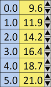
Their scale is here: Image

I have configured my RCP like in the config.php file attached.

When I start the car, the RCP display on the computer shows 15.32 while the LED shows 14.7

How can I correct the discrepancy, assuming the LED is correct, as it is hard-wired to the controller?

Thanks,

Jake
Attachments
config.png
config.png (44.15 KiB) Viewed 1086 times

rocket6706
Posts: 23
Joined: Fri Oct 24, 2014 11:49 am
Location: Seattle

Scaling

Post by rocket6706 »

attached is a typical scaling for a Wideband O2 Sensor. Since the output is linear you could use a simple ratio to bias the line of the Display to the Line of the RCP based on known values (i.e, known display of A/F ratio and measured voltage). If 2:14.2 = X:14.7 solve for X and plug it into the RCP. Once you have three points you have a straight line.
Attachments
Typical Sensor Calibration.
Sensor Calibration.JPG (32.13 KiB) Viewed 1080 times
Rocket 6706

brentp
Site Admin
Posts: 6277
Joined: Wed Jan 24, 2007 6:36 am

Post by brentp »

when in doubt, use a meter to directly measure the voltage right at the terminal block of RCP - then the mapping should turn it into real-world value.

You can bypass the sensor and just use a 3 legged potentiometer to create a voltage divider between vRef and ground - as the voltage sweeps between 0-5v your scaled value should change accordingly as well.

Looks like you're on the right track overall!
Brent Picasso
CEO and Founder, Autosport Labs
Facebook | Twitter

Post Reply