Page 1 of 1
Tapping existing vs using ECU outputs vs new sensors vs RCP
Posted: Wed Oct 29, 2014 7:26 pm
by aaronvogel
Okay guys, so I've been searching and reading around the forums some, have gleaned a little info, and made some of my own conclusions but I still would like to hear what everyone else would suggest for this situation:
I'm currently replacing all stock gauges with aftermarket ones in my track-only CRX. The engine and ECU are OBDI out of an Acura integra. All the existing senders work. I'm also installing the MK2 Race Capture Pro when it arrives next month. So I'd like to do all the wiring and sensor installs at once for both the gauges and the RCP.
Here's the gauges I'd like to install:
Tach
Speedo
Water Temp
Oil Temp
Oil Pressure
Voltmeter
Fuel Level
I'd like to have all that info additionally available in RCP and through Race Capture. Additionally I'd like to have the following in Race Capture:
Throttle position
Brake Pressure (I know this will need to be a new high pressure sender tapped into the brake line somewhere).
Thanks for your input!
So, my question is: when installing the gauges and RCP, which sensors would you A) Tap into from the sensor wiring B) Tap into the ECU signal out to the cluster C) Install new, dedicated sensors or D) Use one of the outputs from RCP
Posted: Thu Oct 30, 2014 8:45 pm
by dimondjack
I would use ECU sensors whenever possible. They are well proven, easy to troubleshoot (you probably have a wiring diagram) and cheap to replace. Remember that the RCP has a resistance when you connect it, so you'll end up changing the sensor value slightly (RCP1 was 10k, I don't know about RCP2).
Speed may be one that you can output from the RCP based on GPS speed. I would be interested if you figured out the speed pulse rate for the speedo and then wrote a channel to match it from the RCP.
Posted: Thu Oct 30, 2014 10:44 pm
by brentp
+1 ECU style sensors are preferrable. We have a list of suggested sensors here:
http://www.autosportlabs.net/RaceCapturePro_Sensors
But of course, with the correct mapping any sensor can be used.
Let us know how it works out!
Posted: Sat Nov 01, 2014 9:08 pm
by aaronvogel
I might not have been totally clear in the original post. There were a lot of implied questions.
But, since I've pretty much worked out everything, I'll directly ask 2 things:
1) Can the fuel level sender be routed to RCP, then out again through an analog output to the gauge?
2) Can the TPS be routed to RCP, then out again through an analog output to the ECU?
Those are the only two gauges I can't use multiples of or tap off since they're resistance based. I want to be able to monitor fuel in the pits, and obviously TPS for driving analysis.
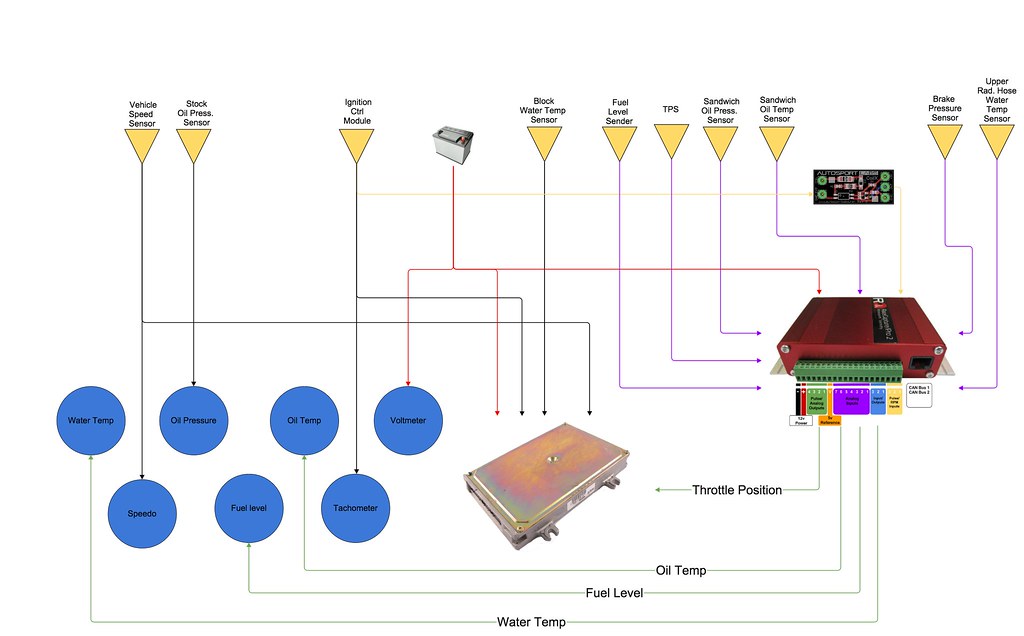
This is a little connection diagram I've put together. If you see anything that won't work or could be done better please let me know.
Posted: Mon Nov 03, 2014 5:16 pm
by brentp
We don't recommend putting RCP into the loop of your ECU and gauges in that manner.
What I would recommend you doing is if you need higher input impedance, then I would recommend an op-amp buffer circuit to isolate the RCP input from the multiply tapped sensors. This buffer would be between RCP and the sensors.
The buffer circuit you want is a 'unity gain' buffer, as described here:
http://www.facstaff.bucknell.edu/mastas ... uffer.html
We have a design here that can be built as well, if you're up to it:
https://github.com/autosportlabs/analogBuffer
Posted: Mon Nov 03, 2014 5:25 pm
by aaronvogel
Brent, thanks!
So water and oil temps are easy to sort out with additional sensors. I was originally planning on doing that anyway.
With TPS and Fuel though, how are other people doing this? Is everyone using the method you mention or are there other methods?
If it isn't already painfully clear I'm an electronics newb. I can wire a stereo, but proper electrical circuits still confound me.
Posted: Mon Nov 03, 2014 5:29 pm
by brentp
Most people tap right into the fuel sender and TPS as the input impedance on RCP is high enough to not cause a problem.
Have you tried doing it already and did you notice any adverse effects on the operation of your ECU or gauge?
Also, when calibrating your fuel sensor, you will need to do a 2 step test where you measure the voltage coming from the sensor when A) the tank is empty and B) when the tank is full.
Then, you can come up with a map that will help you calibrate the 0-100% scale.
If you take these measurements and post here, we can help you create that map.
Posted: Mon Nov 03, 2014 5:36 pm
by aaronvogel
Honestly, I haven't tried tapping/measuring anything yet. I've just been trying to prep as much as possible so there aren't any big surprises when I do the install of everything. I'll go ahead with the assumption that I can tap these two and just look for issues.
I have what the stock fuel sender readings are "supposed to be" but I'll do the 2-step to get precise ones. And I bought a fuel gauge that can also be calibrated.
Thanks! Can't wait to get my hands on the MK2 to actually do the install! I'll have wires waiting to be plugged in.

Posted: Thu Dec 18, 2014 11:38 pm
by brentp
Do keep us updated! We'll be documenting a how-to for manually calibrating sensors, as well as building in the tools to make calibration easier. Right now, as you've figured out, you will need to map a low and high voltage reading and translate that into the linear map in the software. Working on making it better!