How to do custom scaling for analog inputs?
Posted: Fri Apr 12, 2013 12:58 am
How exactly are the raw values converted to voltage so the voltage can be converted to physical units?
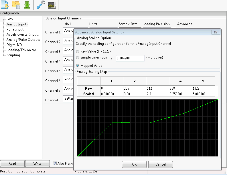
Since the analog inputs are 0-5V, is 0d (raw) =0V and 1023d=5V?
For example, if I wanted to log the wideband O2 sensor signal from an Innovate Motorsports LC1 where 0V=7.35AFR and 5V=22.39AFR I would configure 0 raw =7.35AFR and 1023 raw = 22.39AFR? And must monotony be observed, or could I put 0d=7.35AFR in slot 1 and 1023d=22.35AFR in slot 2 and then 1023d=22.35AFR in slots 3, 4, and 5? Or do I manually need to interpolate the points so that 0d=7.35AFR in position 1 and 1023d=22.35AFR in slot 5 with a straight line between them?