
This is by no means intended as a “how to” guide or anything like that, but rather as a guide showing how relatively straightforward it has been. Hopefully some people who may have been considering going the same route but put off by the “complexity” will be encouraged to give it a go.
(This was originally written for another forum, so it does refer back here quite a lot.)
Apologies for it being so long winded, but I do promise some pictures along the way
Some background…
The vehicle:

The vehicle that the MJ has been fitted to is my B-Reg 90. This left the factory as a 2.25, but in Nov 2008 I changed that for a 3.5 I had rebuilt.
To enable me to afford to run the v8, I had previously converted the vehicle to run on LPG. The V8 is basically standard a 3.5l engine built from a 9.35:1 compression SD1 block, with 4.0 heads, a standard 3.5 EFi cam and 3.9 cast manifolds. Fuel is provided via SU’s when on Petrol, or through the mixer rings when on gas.
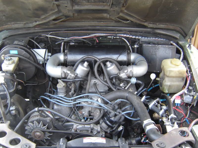
Gas mixture is controlled by a closed loop system, using a heated narrowband lambda located in the y-piece of the exhaust. A stepper valve between the vapouriser and the mixer rings opens/closes dependant on mixture requirements.
The owner:
Me. I have no background in electronics although I am a mechanical engineering graduate, and at points my course did stray off into electrickery. I have not really soldered since I did my GCSE’s…and I did those over 10 years ago!
It was for this reason that I was slightly apprehensive of soldering the small surface mount components in the Megajolt kit. I needn’t have worried however, as you will see later.
The reasons:
Running the v8 on gas with the distributor was fine, I had done the usual thing of advancing timing until it would just pink under load on petrol and then left it at that. I ran the 2.25 this way for about a year with no problems, and the v8 for another 6-9 months after that in a similar way.
However, I wasn’t happy that I was getting the best efficiency from the LPG with the timing setup this way, as it could only ever be a compromise at best. I wanted to be able to run both fuels with ignition timing optimised for the different characteristics of each.
Megajolt would allow me to do this (as Megasquirt would also I think) as it has the ability to switch between ignition “maps”.
Bonuses of fitting the Megajolt would be the better spark from the Ford EDIS system, and the v8 should (although I am still yet to test) be more waterproof in terms of the ignition system.
The final decider was that the mechanical advance on my dizzy went Pete Tong, and a new one if not repairable is about £125…
Finally- why MJ, and not MS?
Well I decided to plump for MJ as I am on carbs and so cannot control fuelling on petrol (I can hear the EFi people yelling “Literally!!” already
I have plans to go EFi, but not just yet as I lack the time. By going Megajolt I could get all my ignition maps sorted, and the EDIS half of the wiring in place and working. It was also less money for me to waste if I made any major cock-ups with assembly!
The basics:
In essence getting Megajolt installed and working involves getting two systems up and running.
The basic “bottom level” system is the Ford EDIS system. This was fitted to fords during the 1990s and early 2000’s and stands for “Electronic Distributorless Ignition System”.
The EDIS system uses a toothed trigger-wheel and sensor mounted on the crankshaft pulley to generate a sine wave that the EDIS module monitors. The trigger wheel has one tooth missing and the EDIS uses this “blip” to work everything out. The EDIS module is connected to the coilpacks and fires them at the appropriate time.
Without a higher level ECU talking to the EDIS, it will run the engine at a fixed 10deg BTDC, which is limp-home mode.
The Megajolt is then the “higher” level control that talks to the EDIS and tells it when to fire based on the ignition map that you have programmed into it. This is connected to the EDIS via two wires, the “PIP” and “SAW”.
For more info on how EDIS works, go here:
http://www.megamanual.com/ms2/EDIS.htm This is aimed at MS users, but the EDIS works the same.
What you need:
Megajolt unit- kit or pre-assembled the choice is yours!
EDIS module with connector and “pigtail” of wire, coilpacks, VR sensor
Triggerwheel
Bracket for VR sensor.
The Megajolt kit
See www.autosportlabs.com for details on features, assembly, operation, ordering details etc.
Megajolt forums can also be found here if you go to the “community” tab.
You will need to decide which method of load sensing to use. You can go MAP (Manifold air pressure) or TPS (Throttle position sensor).
See here for more info:
http://www.autosportlabs.net/index.php? ... MAP_or_TPS
You will also need a cable to go from the laptop to MJ (RJ11> DB9). I made a cable the first time, but bought one when I did my Dad’s MJ- it was not worth the hassle for the price…
The EDIS module and associated coilpack/s and VR sensor.
EDIS4’s are easy to get in the UK for anyone doing a four pot from ebay or a scrapyard (Escorts, Fiestas, Mondeos etc), and EDIS6’s do show up on ebay.co.uk sometimes (fitted to Ford Scorpios and Galaxies?).
For anyone with a V8 you will need an EDIS8 module, and two standard coilpacks as fitted to the 4cylinder models.
I got my EDIS 8 from the “ebay motors” section of ebay.com for just over £30 with delivery. I was lucky, I think £40 is more the standard going rate…
Make sure that you get the connector for the EDIS module with it- also ideally you want to buy one with a nice length of wire attached to it although if you get one with only a short length its not the end of the world.
A trigger wheel and bracket for the VR sensor.
Some people make their own 36-1 trigger wheels and brackets, and there are some vehicles you can also take the standard Ford trgger wheel from, I was lazy and bought mine from www.trigger-wheels.com
You’ll also need some wire of various colours and gauges, including some shielded two pair for the VR sensor to EDIS connection, connectors, a small soldering iron (if building the kit) some tweezers, a good light source, and a steady hand…
Step 1 – assembly of MJ:
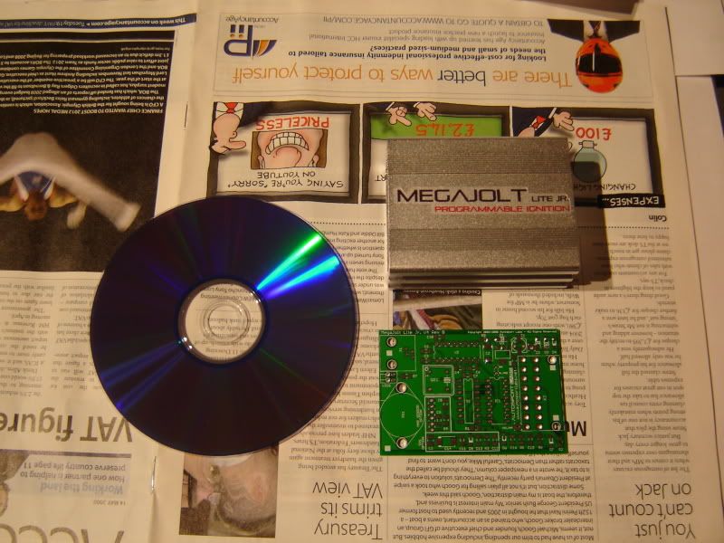
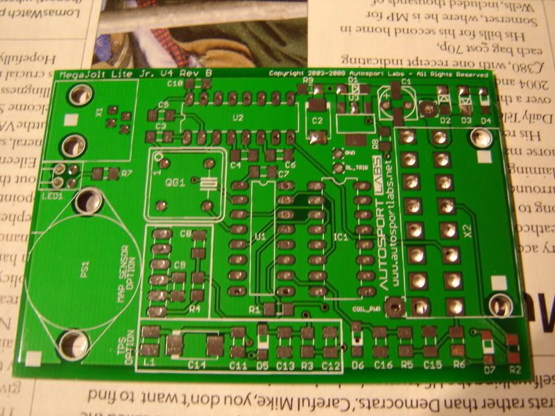
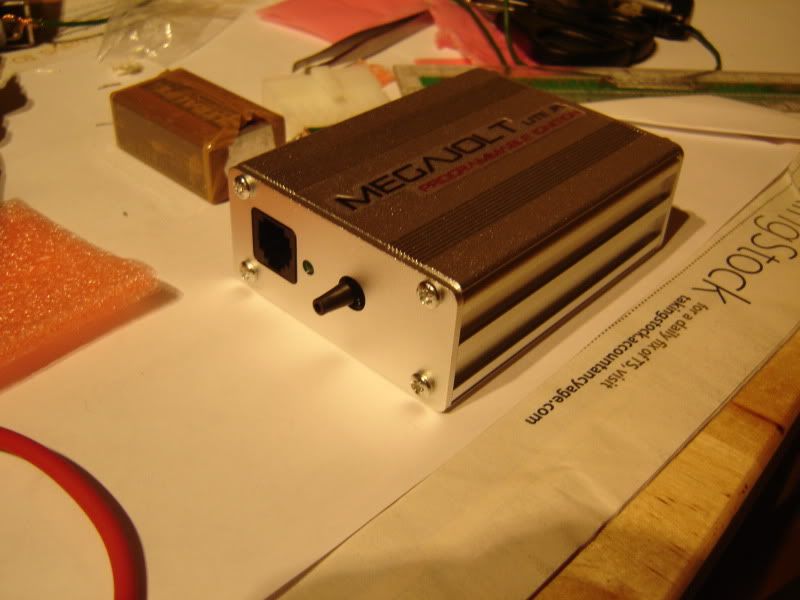
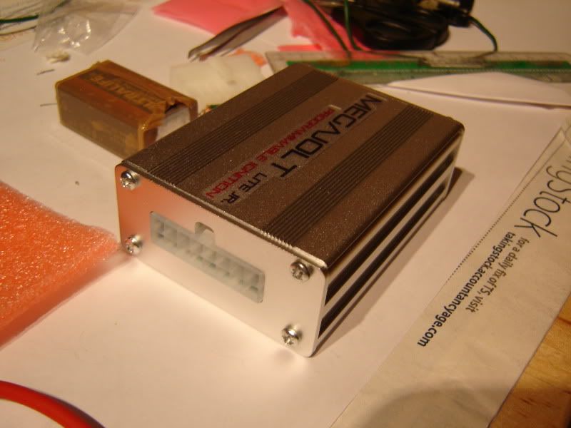
When the MJ arrived I was slightly shocked at how small it was, I had imagined it to be slightly bigger. Panic about soldering it all began to set in. Here it is next to a DVD for size comparison:
Everything is packed in neatly labelled bags, so you only unpack the components for the section you are working on:
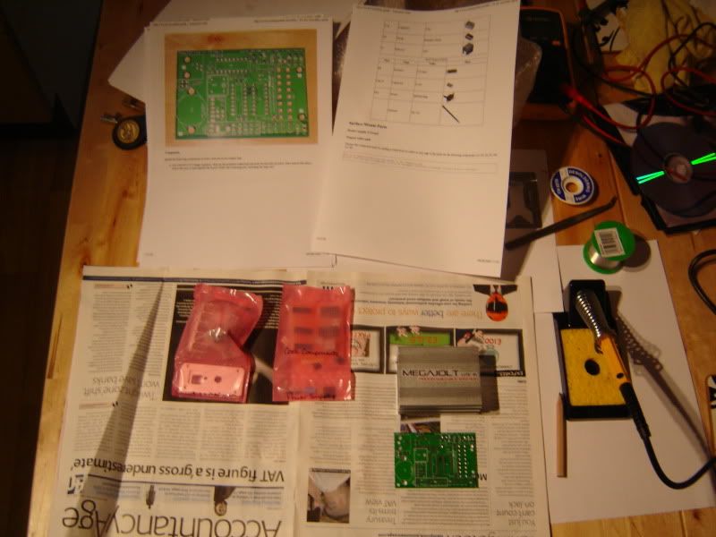
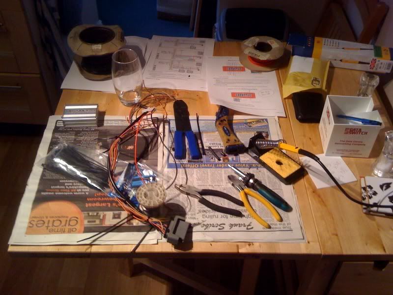
And my workbench (AKA the kitchen table
Print out the instructions from here and read them- they are excellent:
http://www.autosportlabs.net/MJLJ_V4_kit_assembly_guide
Make sure you have a nice well lit area to work in, with a pair of good tweezers and some decent free flowing solder (I had a nightmare with some new lead-free stuff and so reverted to some “proper” solder I got from my Dad). I used a tiny 12W soldering iron that I got from Maplin to do the job.
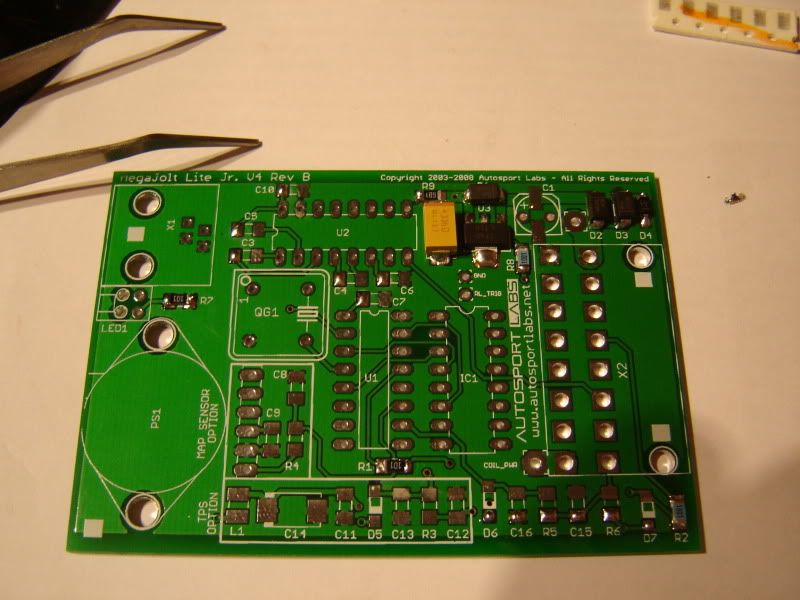
You begin with the power supply circuitry. Follow the instructions and firstly add a small blob of solder to ONLY ONE pad of each component you are set to solder.
Don’t apply too much. Here’s mine (first components to be fixed are top right):
Then to fix the component, reheat the solder on the pad you did, and slide the piece onto the board flush using the tweezers. Once that has set and you are happy with position, heat and solder the other side:
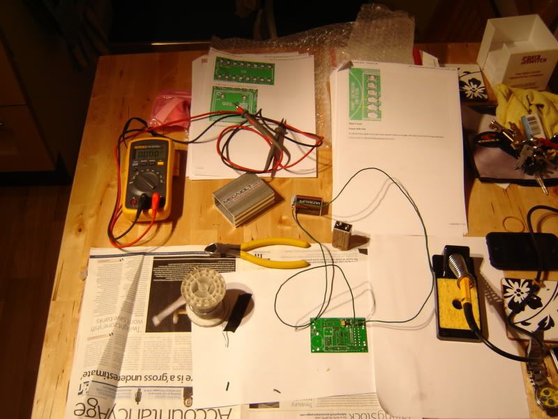
Then work on through the instructions, stopping to test voltages as specified. You will get this:
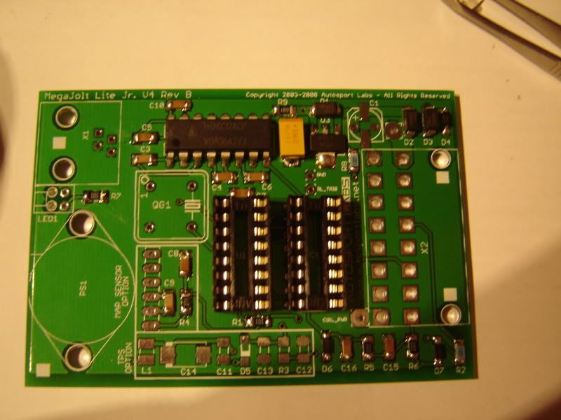
Then this:
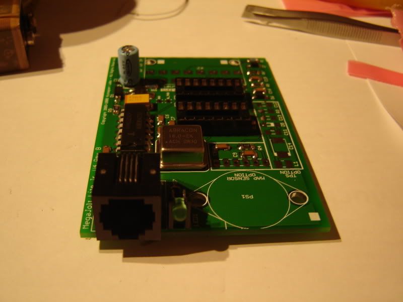
And eventually this:
If you verified voltages along the way and had no disasters then you should have a working MJ unit!
Once you are going it is really quite therapeutic
To test, download and install the Megajolt software from here:
http://www.autosportlabs.net/MJLJ_V4_Downloads
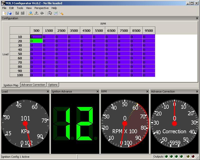
Connect your MJ to the PC/laptop with the cable, power it up (I used the 9V battery I used to test voltages) and open the software. If you have a MAP sensor you can suck on it and see how the pressure reading changes. If it does, congratulations! Remember that the normal pressure will be around 100kPa:
If you are using TPS, then you can’t do that, so try retrieving the controller’s current settings by clicking the little blue arrow icon, just below “view” on the toolbar. This should display the map that the controller has on it by default.
If you are having issues with communications between PC and MJ, then try posting on the autosportlabs forums, beware that if you are using a USB-> Serial convertor device then some of these do give problems. The autosport site has details of the tested working ones that are on the market.
Wiring EDIS to MJ
Read this first:
http://www.autosportlabs.net/MJLJ_V4_v ... tion_guide
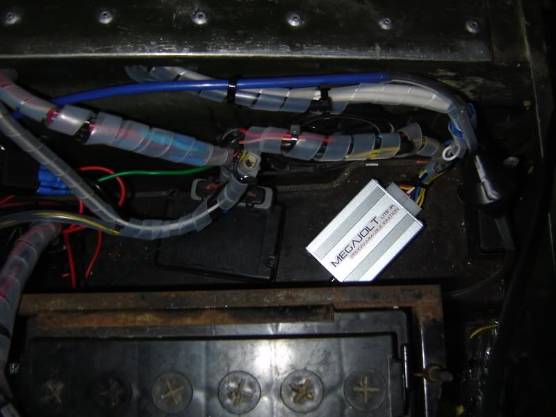
This next step depends entirely on where you want your EDIS and MJ units to sit. I opted to put mine in the battery box, mainly because it’s nice and warm and dry in there usually and you are ideally placed for live feeds etc.
If you wade a lot then I recommend lacquering the MJ board and putting the whole lot somewhere a bit higher!
With this in mind I began making up the cable that would join the MJ and the EDIS. I decided to make it around a foot long so that I could move the units about a bit. Start by consulting the diagrams on the Autosportlabs site. BE CAREFUL WITH THE EDIS8 DIAGRAM it is easy to get everything backwards… Ask me how I know :ph34r:
Use this to help get things clearer:
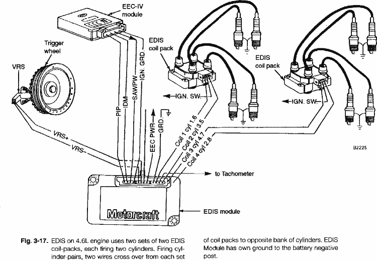
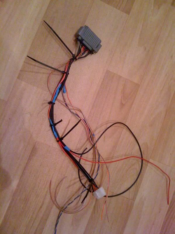
I used a lot of cable ties during this phase to hold everything together as one big cable. I twisted and soldered the wires between connectors, before heat-shrinking the joints. I know some people say that this will fail in a car due to vibration, but I still feel better about a soldered connection than a crimped one if the connection isn’t one that needs to ever be disconnected.
The MJ and EDIS only need to have the PIP and SAW connected between them (the MJ instructions recommend shielded wire), but I decided that as both should be earthed and powered from the same point that they should be joined also, giving only one connection to the power supply and earth point. This included the grounds from the shielding on the VR sensor wire, and the PIP and SAW.
Along the way you will end up with something like this:
So that’s the fun, warm, dry and clean bit all done. Time to head outside to the Landrover…
Trigger wheel and sensor
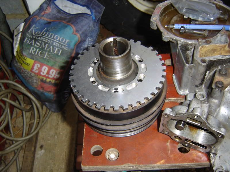
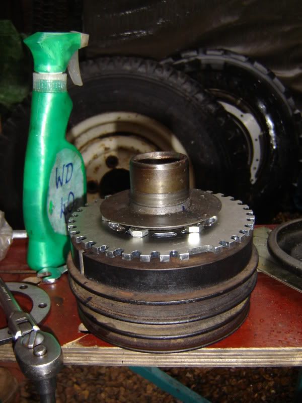
Take your trigger wheel and ensure that you have the right one. My pulley has 6 bolt holes, which is what my trigger wheel is made for, so that’s all good:
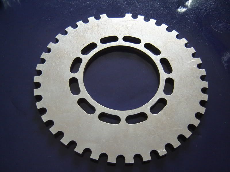
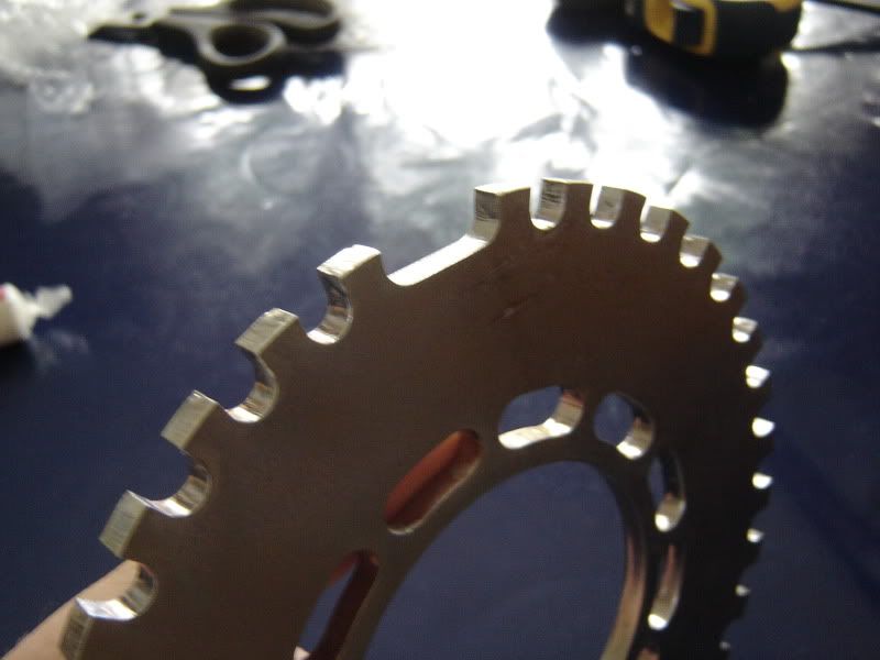
Missing tooth:
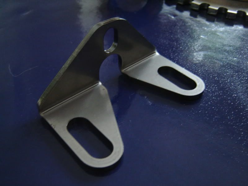
VR sensor mount:
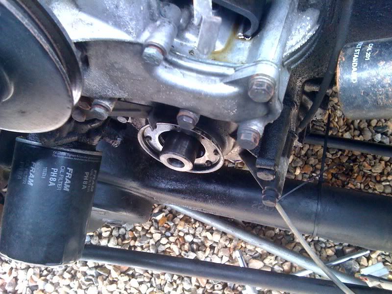
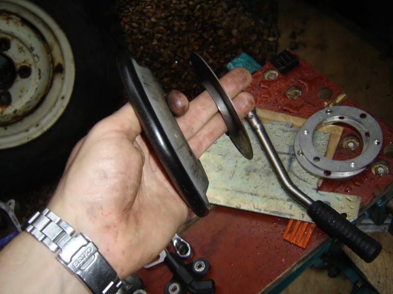
Remove your fan belt and then the bottom pulley- mine came off easily as copper grease had been applied when the engine was put together, and it had only been on there a short while anyway
(Please ignore the oil leak from the timing chest collecting by dizzy, I used a rubbish gasket and it has haunted me ever since…)
Pulley as removed:
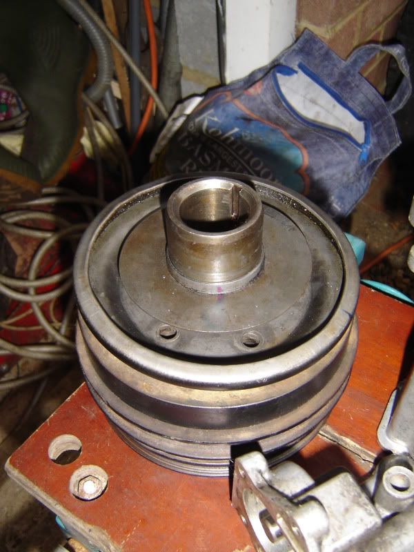
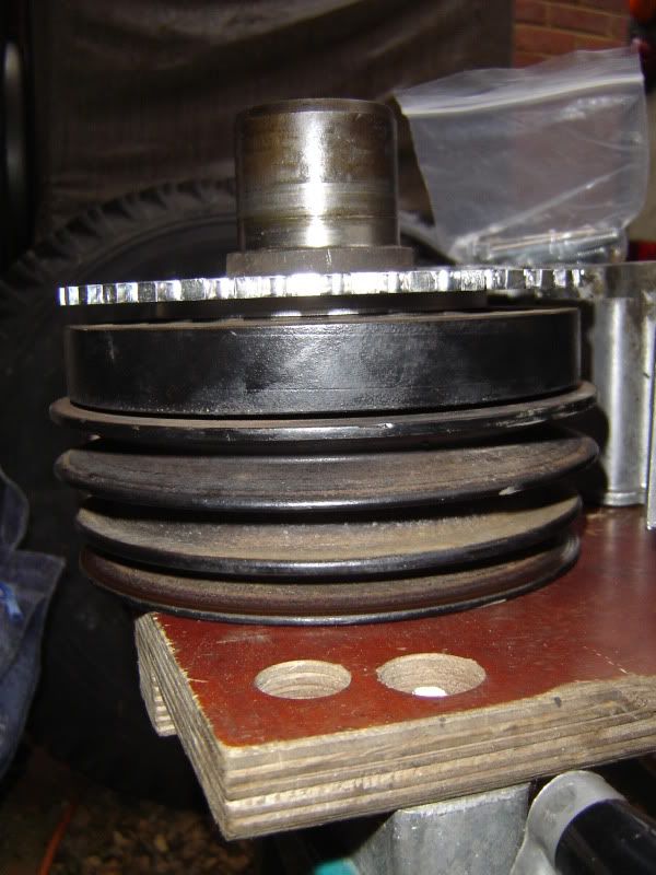
Carefully remove the mud shield thingamby whatsit:
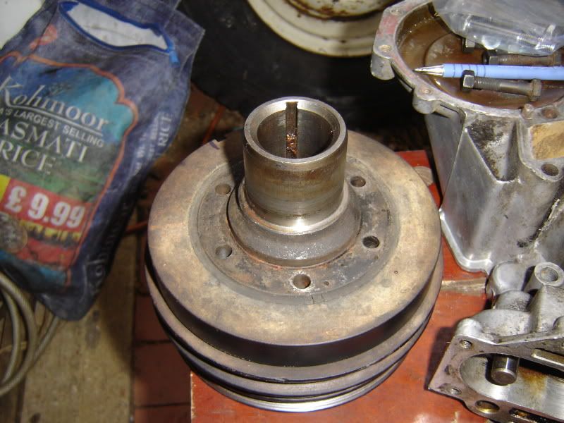
Affix the trigger wheel, using spacers as needed. I had to use only one of the two that came with my wheel.
Spend time working out and checking the alignment of the missing tooth with relation to the position of the VR sensor! This is all in relation to cylinder #1 being at TDC. For the V8, the missing tooth passes the sensor 50 degrees or 5 teeth BTDC. Double-check the installation guide if you are unsure, or want figures for other cylinder configurations:
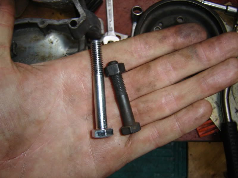
You will probably need longer bolts, so make sure you get some first- I forget what they were, but will update this if I remember. Here’s a pic comparing old and new:
Once in position, reassemble with the mud shield thing back in place:
And refit to engine:
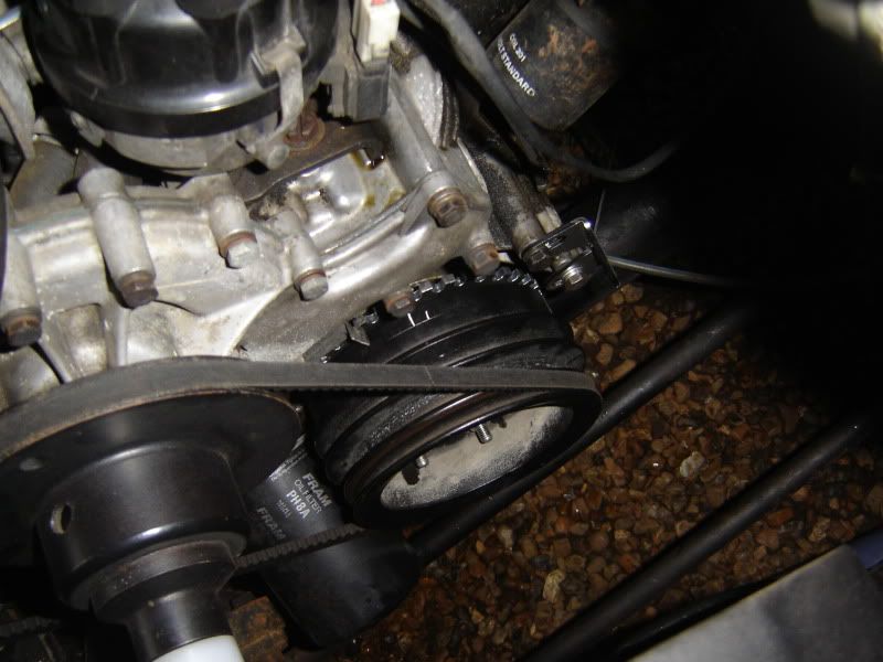
Attach the sensor, and position as close to the wheel as you can without it touching.
Coilpacks:
I followed the tried and true method of mounting my coilpacks above the waterpump. As per this thread:
http://forums.lr4x4.com/index.php?showtopic=25256&st=0
The bracket was made from some old aluminium that was part of a server cabinet
Unfortunately none of my ebay bargain coilpacks came with a connector, but you can’t really grumble when two of them came in at £5 with shipping! I therefore had to buy some new ones, which were sourced from trigger-wheels.com.
I worked out how much wire I would need to run back to the battery box in one hit, then attached the connectors. I cable tied the wires together to form two separate leads for the coils, then spiral wrapped them together as one.
This was routed to the battery box, and is connected to the EDIS with some bullet connectors. I would use some nice threeway connectors next time for neatness.
Map sensor connection
I took the MAP sensor reading from the hole on the drivers side of the inlet manifold, behind the carb. On my manifold, this hole was blanked off with a bolt but on a spare manifold I had there was a banjo fitted in its place. I used the banjo and some nylon tube to reach the battery box. Between the manifold and the MJ I inserted a small reservoir to smooth the signal. This was constructed from two tiny cooking funnels about 1.5” in diameter that were glued together (you can see it wrapped in insulation tape in the battery box pic further on)
Battery box connections
With the coilpacks in place, the trigger wheel mounted, and the EDIS and MJ plugs wired together all that was left was to connect it all and try to fire it up on EDIS alone…
Power was taken from the 40A relay that I have already installed in the battery box to provide power to the lambda heater and LPG kit when the ignition is on. Earth was taken directly back to the negative terminal of the battery.
HT leads were (and are still) a lashup mix of standard 8mm Rover leads and the Ford leads that came with my coilpacks.
The Rover leads are bodged on using “hotwire” adaptors I got in Halfords. I was going to order a proper set from Fastlane but will now be waiting until my dad has his MJ installed so that we can order two sets at the same time. Avert your eyes now if you are easily disturbed!
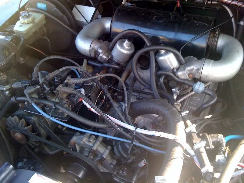
And lo and behold it fired up first time! So well infact that I thought I must have left the dizzy connected or something! Idle was much smoother and more stable- and it didn’t run badly at all before!
I checked the timing and found I was out 2 degrees. I decided not to physically correct this, and instead opted to adjust it out in Megajolt later.
Next step was to connect the Megajolt and verify that the timing is advancing as it should. It was! Hoorah!
Right, so time to comment on the general running since Megajolt was installed.
Quite simply, it is just unbelievably good. The 3.5 was never slow to start on petrol, but now will always (and i do mean always start before the engine has cranked twice. That is from stone cold, after sitting unloved for days and this is starting on petrol or LPG. Before the MJ I would sometimes struggle to fire up from cold on gas. Not anymore! In these last few weeks I have been starting on gas from cold after being stood overnight when the temps have been -6°C
As I said before, the idle was now rock solid. Totally. It pulled better, and after I had got a map from the internet it was needing less throttle and returning better mpgs… Result!
So, first thing on my agenda was to get my "map switching" sorted. This allows the ignition map to be changed during running, and in my case was to allow the engine to run specific petrol and LPG maps.
The map is switched when a certain pin on the MJ is grounded, as shown here:
http://www.autosportlabs.net/MJLJ_V4_ve ... ion_Switch
And what most people do is have this on a switch, however I wanted it to be switched automagically. What i did was use a small SPDT relay from Maplin wired up like this (a SPST would have done):
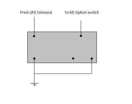
*the legs may have been in a different orientation, but you get the idea*
This is located in my LPG wiring box and was wired to take a feed from the LPG solenoids, so that when they are powered (and hence you are on LPG) the relay is triggered and the MJ option is connected to Earth. In this manner the correct ignition map will always be selected for the fuel you are running. This is not only convenient, but safer too as running a map written for LPG whilst actually running the engine on Petrol could be very bad indeed. :blink:
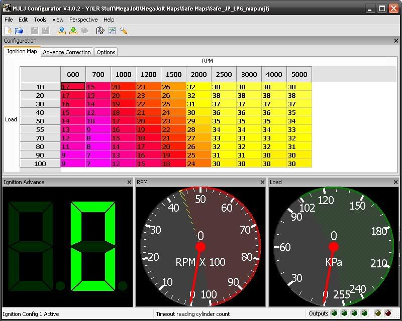
So now that I could write to differing maps i set about getting my LPG map sorted. I started out by using the "standard" 3.5 petrol map that is in the megasquirt thread and then adding more advance. I then tried a map I found on the Megajolt forums written for a 3.9 running gas, and that worked well. However in the end Ii ended up tweaking that too, as reading around the general consensus on the v8 forum was that you can get all of your timing in on a 3.5 by around 2500rpm. Initially i didn’t really do much tweaking but spent my time driving about and getting a feel for what parts of the map i was hitting when travelling about. From this i then began tweaking the areas I spent the most time in and going from there.
Eventually I got to this map for LPG, and I am still running the original petrol map for normal running.
Now that I had the map more or less sorted i now turned to address an issue that had been bothering me since i installed the closed loop addition to the LPG. If you have a vehicle that runs a throttle position sensor then the control box can be adjusted so that the system goes "open loop" at idle. As my carbed engine did not have a TPS this meant that my system was running closed loop all the time and giving me some annoying hunting when stationary.
As the lambda control box is adjustable, i came up with the idea of using the MJ to trigger open-loop mode when idling... After posting on the Megajolt forums, my plan was to do this:
Using a user defined output from the Megajolt, i could connect this to the lambda box and it would see 0V when this output was triggered. (All megajolt outputs switch to earth, rather than switching some voltage). To prevent the box from seeing some random floating voltage when not idling the +5V from the Megajolt TPS ref pin is connected to earth via a “pull up” resistor:
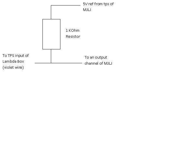
Thus the box should see ~5V or nothing at all. See my original thread for more info:
http://www.autosportlabs.org/viewtopic.php?t=2518
All that was left then was to set the output to trigger in the Megajolt software- I used output #1.
I decided to use RPM, as at the time my MAP reading was spiking a bit here and there:
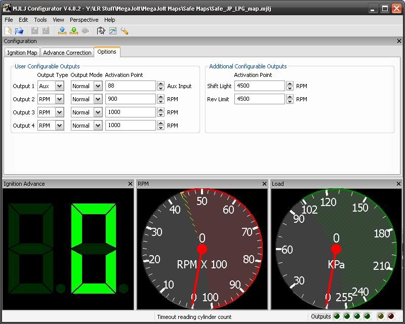
And finally tweak the adjuster on the LPG box until the yellow light went off when the car was at idle and the output was on. Sorted!
The vehicle no longer hunts to the degree it did, although it still does a very small amount. Apparently to eliminate this entirely I would need to connect my crankcase ventilation to the air intakes, upstream from the mixer plates. I won’t bother though as for the small improvement to be gained, I don’t think the effort is worth it.