
This is a bit of a how-to, and a bit of a how-not-to. I don't have my own camera, and haven't been able to borrow one since I finished, so all the pics are of the build. Proof it works will follow. Promise.
It all started when brother took my Mini for a drive. Result - a bad knocking whilst cruising. Took it to my local mini people, one of whom said "you've got a loose tappet". "No I haven't" I said. At which point his son came out of the rollers bay munching on a salad, mumbled "big end" and went back in again. At least I know what knackered big ends sound like for next time.
Anyway, this is what was in the bottom of the drain pan. Not a great pic, but the silver bits are what turned out to be no3 big end (mostly).

Long story short, 10 thou undergrind and a few new bits and bobs and it went back together.
Enough about the engine. More about the MJ. Well, trigger-wheels.com did the honours for the EDIS bits and bobs. MK1 coil, 5.125" wheel with 1/2" hole, used plugs and EDIS module. Arrived safe and sound.
First off was making the crank pulley and trigger wheel. The pulley I have is off an MG Metro, so it's of the cast variety. I knocked the old trigger wheel thingy off the inside of it, and put it on the engine (which was conveniently located on the bench - man would I hate to have to do this with the engine in the car). Did some quick measurements, and went off to university to use the CAD software. Made a model of the pulley in situ on the cover and had a look at clearances.
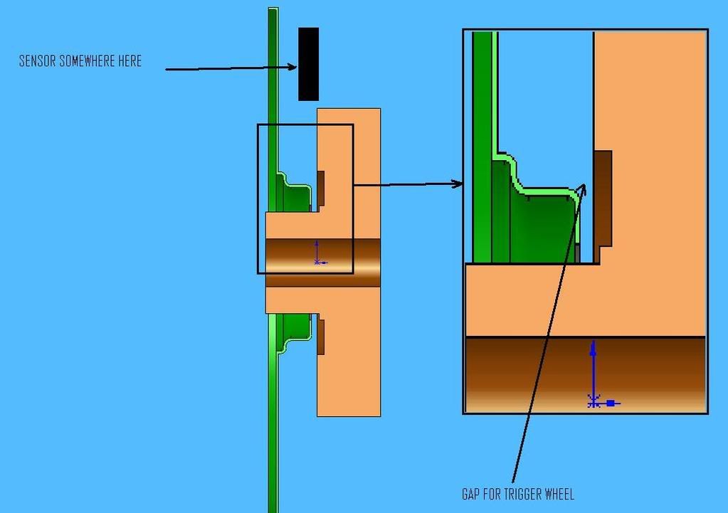
I came up with this design of trigger wheel mount...
...which fitted onto the pulley like this:
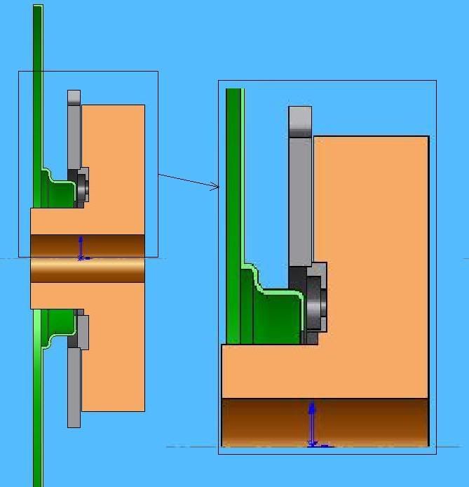
Made out of two parts, it would have a boss bolted to the crank pulley, to which would be welded the trigger wheel. Sounds complicated, but it gave me the clearance (I thought - more later), and meant I didn't have to worry about where I put the holes. I could just make the boss and drill & tap the pulley, then weld the t-wheel to the boss in the right place once I had the sensor mounted.
It meant I had to take the hole in the trigger wheel out to 70mm, which I managed to do on the lathe at University (Ta Keith). Also did the boss, but didn't take any pics.
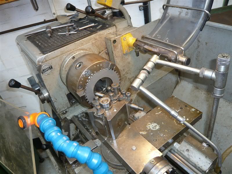
I got it home and offered it up to the engine with the timing cover in place. Surprice surprise it didn't fit. First I needed to grind a bit off the little sensor mount at the rear of the cover, and bent the timing marks flat against the cover - not too hard. Then I found the boss was fouling on the timing cover. Not part of the plan. So after um-ing and ah-ing for half a day, and drinking much tea, I dug this out.
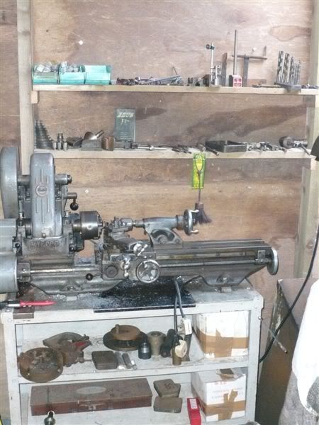
An old Myford we inherited off grandfather which hasn't seen any real use since it arrived. Managed to find an old bit of bar, and turn it down (after studying how to make lathe tools for a few hours, and being busy on the bench grider for a few more). Much tool chattering later, and a bit of filing for the keyway, I had a little 2.5mm thick spacer. This pushed the pulley out more than enough to stop it rubbing the timing cover. Smiles from ear to ear that day, so chuffed was I.
Next step on the Megajolt bit of the build was obviously the sensor mount. A bit of 3mm steel bent into a right angle bracket with a bit of support sorted it. I MIG welded it onto the timing cover so it sat inside the fanbelt.
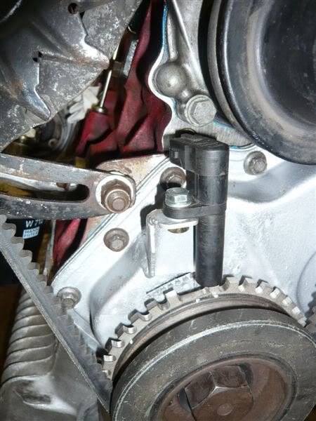
The sensor bolted on with a single M6 nut and bolt. It was a pretty loose fit in the sensor, which had an 8mm hole, so I had some side to side adjustment. I was a little worried about how floppy the sensor seemed to be. Presumably the sensor itself has a little tube to sit in on the Ford it came off, but it seems to be OK so far.
The pictures are a little misleading as they weren't taken at the right time. At this stage of the build I had the engine on the bench with no head on and no gearbox. I put the timing cover on and fitted the sensor. Then bolted the boss I had made earlier onto the pulley, put the trigger wheel in place and slipped it onto the crankshaft. I then set No1 cyl to TDC with a dial gauge, and rotated the trigger wheel until it was lined up right.
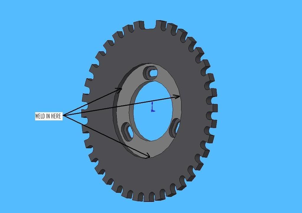
I had previously stamped a helpful "9" into the 9th tooth after the missing tooth. I lined this up with the centre line of the sensor and marked the trigger wheel against the crank pulley with a Tipp-ex pen. Took it all off, and used a centre punch to put a permanent mark, right where the boss joined the trigger wheeel (marked with the arrows labeled "WELD IN HERE" on the pic above). This made the previous sliding fit between the two into a bit of a bodged interference fit, so they stuck together. I took this opportunity to double check it all lined up properly, then have a cup o'tea, then triple check.
To minimise any risk of distorting the trigger wheel when welding it to the boss, I roasted the two at gas mark 6 while I had my lunch. Finished lunch, lined up the centre marks (good welding gauntlets required here) and MIGed the two togeher with 3 small beads in between the mounting slots. Once it had cooled, I bolted it all together and got on with the rest of the engine build.
Before I put the engine back in, I had a go at mounting the coil and EDIS, and making the loom. Put the coil on the bulkhead and the EDIS tucked in quite nicely (read tightly) next to the wiper motor. Coil was mounted on four 14mm dia, 20(ish)mm long posts (made on the Myford again), with an M6 thread down them. Bolts through the bulkhead from the cabin stuck them to the car, and 4 pan head allen bolts through the (drilled out) coil bolted it to them. Easy.... if you happen to have a lathe lying around! I had to remove the wiper motor to put the EDIS in place, but with the engine out, this wasn't awkward. Again, I am very glad the engine wasn't in for any of this.
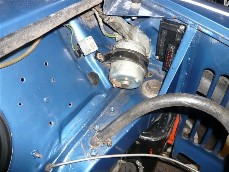
You can see the EDIS here, and the holes for the coil mount.
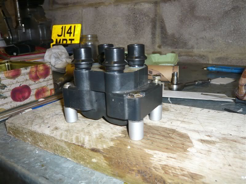
This is the coil on its mounts on the bench. I thought I had a pic of it in the car, but it appears not.
Making the loom up was a bit of a hassle. All entirely self inflicted though. I thought it would be fun and look tidier if I took all the old wires away and made up a new loom reusing the terminals. Bit of an error. Not Knowing how these things came apart, I managed to bugger up entirely the sensor plug, and break off one of the tabs on the EDIS plugs. Silly boy. A new sensor plug was cheaply available from Vehicle Wiring Products (off that new fangled tinterweb thingy). I fixed the EDIS plug with a bit of superglue on the appropriate terminal, and it hasn't broken yet.
I should have spent more time on the internet looking for instructions on how to take the multiplugs apart, but I was getting impatient. For those of you like me, the EDIS plug is fairly easy. Take the red bit of plastic out, then slip something small and pokey down the hole it came out of, jiggle it about. Threre is a small plastic tang that needs lifting up into the space vacated by the red plastic locking thingy you just removed. Fiddly but doable. However, I ended up just soldering wires onto the little tails I had removed. Looks OK with a bit of heat shrink over it.
Another mistake I made was to try and make all the other wires end at the EDIS plug. Being the biggest, it was really hard to get them all the same length. I'm guessing Loom Construction lesson one is "Always start from the biggest multiplug".
In the end, it worked out OK. I can heartily recommend using nylon braided sleeving and heatshrink. The braiding is very flexible and easy to push wires down. Much better than convoluted tubing and easier to feed wires down than PVC. Just watch out for frayed ends and the way it changes length depending on how fat it is.
So once the engine was back in and I had oil pressure, I plugged in the coils and tried to fire it up. Nothing, just a load of blowing back up the carb. Double checked I had the trigger in the right place (found rough TDC with a bit of wire down the plug hole, and counted the teeth as I turned the engine manually). Then used this to make sure I hadn't completely buggered up timing the cam. All good. So I swapped 1 & 4 leads with 2 & 3, and off she went. This stretched the plug leads so I had to swap the wires over on the EDIS plug, which was awkward to say the least. I must have misread the wiring diagram when doing it in the first place. Managed to fluke getting the VR sensor plugged in the right way round though so not all bad.
Had a quick check with the timing light, and the spark was somewhere between the 8degree and 12degree marks. In my book, that's 10degrees. All I had to do was wire in the MJ and go mapping.
So that's how I did it. The big question is, 'would I do it like this again?' The answer to that is: 'er maybe'.
The clearance between the timing cover and the boss was always going to be tight. Making the boss took a while - turning it down, milling the slots, counterboring them etc. And in the end, it didn't fit. If I didn't have a lathe handy, and a bit of scrap bar, I would have been in for another wait while someone else made one up, and it would have been just another bill. In short, it would've been a right hassle if I didn't have the benefit of 2 generations worth of amateur engineering facilities at my disposal, as well as a University workshop. If you want an easy install, weld the sensor to the engine mount plate that bolts to the gearbox, and have someone turn a shoulder onto the outside edge of the pulley. Much easier I reckon.
However, it is quite a tidy install. Everything is quite compact, and nothing looks like it really shouldn't be there. Making the mount in two pieces was a good idea I reckon. It really took the pressure off when I was drilling and tapping the crank pulley.
The only really awkward thing is looking at the timing marks now they've been bent out the way and someone has put a sensor right in front of them. That would be a right bugger if I still had a distributor.
