
patriq, just to ask the question... what is the trigger wheel made of? pardon me please if i am stating what you already know, but the metal has to magnetic. so it cant be aluminium. stainless steel may or may not be useable, because stainless steel with nickel in it (cant remember the grade names), is not magnetic, whereas other s.s. is. bottom line is that if a magnet wont stick to the wheel, it wont trigger the vr sensor.
looking at the photo, i would guess it is either stainless or high carbon steel. carbon steel would be ok, but if stainless it might well be the wrong type.
could that be the problem?
regards
alexander.
2nd installation : No spark
Moderators: JeffC, rdoherty, stieg, brentp
It's magnetic alright !
Tried with a small travellers chess piece that had a tiny little magnet on the bottom to stick to the board. It attached as if it had always wanted to do that it's whole life !
Both on top, the side and underneath.
So that rules out the wheel. I just got another meter in my hand from a collegue. So next is to measure to se if there is AC from the sensor. Both directly and via the sensor cable.
All those who believe in telekinesis, raise my hand now !
This SS question is pertinent info. Just came in from checking my VR sensor with the drill, and wouldn't you know it I grabbed a stainless bolt first. Then it hit me why I got no AC reading. Grabbed a plain old steel bolt and it registered about .3 vAC!
Also decided to check the coil, but could not get a spark. Used a 12v car battery, and earthed the plug to the battery and also tried a good ground: a cold water pipe. It is supposed to cause a spark when the current is removed from the coil after it charges, right? So if you touch 12v to the coil and remove it, a spark event should happen, yes? Spark plug is a good used one, high-tension lead is good, and my coil reads about .2 ohms primary. Tried both sides. I got a helluva spark to the battery with the coil power leads, though!
Also decided to check the coil, but could not get a spark. Used a 12v car battery, and earthed the plug to the battery and also tried a good ground: a cold water pipe. It is supposed to cause a spark when the current is removed from the coil after it charges, right? So if you touch 12v to the coil and remove it, a spark event should happen, yes? Spark plug is a good used one, high-tension lead is good, and my coil reads about .2 ohms primary. Tried both sides. I got a helluva spark to the battery with the coil power leads, though!
I got just about 0.7V AC as well with a drill and a bolt - but then the sensor is magnetically "attatched" to the bolt. If I hold it as close as I can without it being in constant contact with the bolt I read 0.030-0.060 V ACMartinM wrote:1. Could it have been damaged ?
Unlikely, but possible
Are they fragile ?
No
Is there a way to test the sensor - without the wheel ?
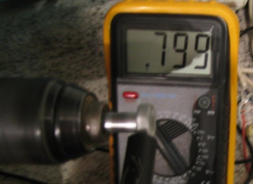
With a 8mm bolt in an electric drill at about 400rpm....0.799volts AC just caused by the hex sides of
the bolt being closer/further from the end of the sensor as it rotates
When I crank the engine and read AC at the contact that attatches to the EDIS unit (at the end of the sensor cable) I read 0.018-0.025V from the same sensor.
Now, this I read was supposed to be around 3V !?
Is my signal way to weak ? And then why ?
If you look at the previous post with images of my converted dizzy - does the sensor seem to be at a proper distans from the wheel ? Does it need to be any closer than that !?
All those who believe in telekinesis, raise my hand now !
My 0.7V AC was just before the bolt attached itself to the sensor as wellPatriq wrote:I got just about 0.7V AC as well with a drill and a bolt - but then the sensor is magnetically "attatched" to the bolt. If I hold it as close as I can without it being in constant contact with the bolt I read 0.030-0.060 V AC
When I crank the engine and read AC at the contact that attatches to the EDIS unit (at the end of the sensor cable) I read 0.018-0.025V from the same sensor.
18-25mV AC is almost certainly not enough for the EDIS - is this open circuit or with the VR sensor connected to the EDIS? Last time I measured mine (5.25 inch mild steel wheel) I got, open circuit, 0.3V AC to 2V AC when cranking.
You normally need about 1mm clearance from sensor to wheel.
Maybe it's the dimensions of your wheel? I'm only used to big 36-1 steel wheels and yours is a lot smaller - not as small as Alexander's though....but I note that he didn't use a Ford sensor, but it looks like you are...maybe there's something in that?
hi martin, patriq,MartinM wrote:
Maybe it's the dimensions of your wheel? I'm only used to big 36-1 steel wheels and yours is a lot smaller - not as small as Alexander's though....but I note that he didn't use a Ford sensor, but it looks like you are...maybe there's something in that?
i just want to clarify something about the wheel/sensor i used. the sensor was specifically designed to read tiny teeth, so in itself it is not a guide to how small a wheel the ford vr sensor can read.
having said that, my intuition (ie all guesswork and no expertise!) is that patriq's wheel is not too small for the ford vr sensor. the info on trigger-wheels.com certainly suggests it should work, and if the slight edges on a hex headed bolt cause 0.7v i would be surprised if the wheel teeth would not! the trigger-wheels.com. site says they have tested a 2.5" wheel (obviously 36-1, however) from speeds of 10rpm up to 26,000rpm, so surely yours should work.
i am still concerned about the stainless steel material. i note, patriq, that the magnetic chess pieces stuck well, so probably that concludes that matter, but perhaps the s.s. is never the less still not creating enough of a voltage spike. i know this would be more annoying delay, but perhaps you might buy one of trigger-wheels.com small wheels as a benchmark? if you sensor gives a usable voltage signal with theirs, then that would make the s.s. one suspect.
regards
alexander.
I measured 18-25mV with the EDIS contact detached - on the pins in the contact that goes into the EDIS-unit.MartinM wrote:My 0.7V AC was just before the bolt attached itself to the sensor as wellPatriq wrote:I got just about 0.7V AC as well with a drill and a bolt - but then the sensor is magnetically "attatched" to the bolt. If I hold it as close as I can without it being in constant contact with the bolt I read 0.030-0.060 V AC
When I crank the engine and read AC at the contact that attatches to the EDIS unit (at the end of the sensor cable) I read 0.018-0.025V from the same sensor.
18-25mV AC is almost certainly not enough for the EDIS - is this open circuit or with the VR sensor connected to the EDIS? Last time I measured mine (5.25 inch mild steel wheel) I got, open circuit, 0.3V AC to 2V AC when cranking.
You normally need about 1mm clearance from sensor to wheel.
Maybe it's the dimensions of your wheel? I'm only used to big 36-1 steel wheels and yours is a lot smaller - not as small as Alexander's though....but I note that he didn't use a Ford sensor, but it looks like you are...maybe there's something in that?
All those who believe in telekinesis, raise my hand now !
It's funny - you have the same thoughts as me. But you get to post them before me on the forum......alexander wrote:hi martin, patriq,MartinM wrote:
Maybe it's the dimensions of your wheel? I'm only used to big 36-1 steel wheels and yours is a lot smaller - not as small as Alexander's though....but I note that he didn't use a Ford sensor, but it looks like you are...maybe there's something in that?
i just want to clarify something about the wheel/sensor i used. the sensor was specifically designed to read tiny teeth, so in itself it is not a guide to how small a wheel the ford vr sensor can read.
having said that, my intuition (ie all guesswork and no expertise!) is that patriq's wheel is not too small for the ford vr sensor. the info on trigger-wheels.com certainly suggests it should work, and if the slight edges on a hex headed bolt cause 0.7v i would be surprised if the wheel teeth would not! the trigger-wheels.com. site says they have tested a 2.5" wheel (obviously 36-1, however) from speeds of 10rpm up to 26,000rpm, so surely yours should work.
i am still concerned about the stainless steel material. i note, patriq, that the magnetic chess pieces stuck well, so probably that concludes that matter, but perhaps the s.s. is never the less still not creating enough of a voltage spike. i know this would be more annoying delay, but perhaps you might buy one of trigger-wheels.com small wheels as a benchmark? if you sensor gives a usable voltage signal with theirs, then that would make the s.s. one suspect.
regards
alexander.
I thought I'd first conclude on other 'thesis' first. But yes - I've also thought about that maybe the s.s wheel is magnetic, but not enough !
Instead of going the route of removing the wheel, have another one made (and more money - the wheel was about GBP £150....) - couldn't it be solved with an amplifier ? Since it is generating voltage.
All those who believe in telekinesis, raise my hand now !
150 pounds!!!!!!!!!!!!! good god!
gosh, patriq, this is getting tricky...
re the amplifier issue: i see also that the trigger-wheels.com site talks about amplifiers, but then you just heading off into the great unknown, unless someone else on the forum has particular expertise in such matters.
so right now, we dont know whether the teeth are just too small for that sensor to read, or possibly the s.s. is a problem (your magnetic chess pieces certainly suggest that is NOT the problem), or it really is the sensor (seems unlikely). so that leaves a few possible courses of action:
*get a 2.5" 36-1 wheel (which is known to work) to verify that it works with your sensor. cost: 30 pounds; if not
*get another sensor; if that doesnt work still, then
*try a mild steel wheel, but not for 150 pounds! and fabricating one is not out of the question, but definitely fiddly; or
*crank mounted wheel (maybe you dont have that option?); or
*get a sensor like i used (if available second hand in norway (FC series mazda rx7 crank angle sensor), and i will post you a piece of the gearstock i used.
patriq, i sympathise .. it is so annoying when these things dont work straight off, especially when you have such cool looking hardware! note: even if i speak like i really know what i am talking about, remember that i dont really
cheers for now.
alexander.
Interesting - I'd not seen the Technical pages at that web site.
They completely fit with my observations of voltages, and they report 3V AC at just 18rpm, rising to 100V AC at 10,000rpm.
Patriq - any chance of you getting an oscilloscope? Measuring with a voltmeter should be OK, but you never know exactly what's going on with these sort of things until you can see pictures of real waveforms. There might be something weird going on that an oscilloscope would show straight away. Shame you don't live 10km from me!
Would an amplifier work? Possibly, but as Alexander says it's a bit of an unknown and you would definitely need a 'scope to see what was going on and help you to build, and verify, one - unless someone supplied one that was guaranteed to work out-of-the-box....I'd worry about the dynamic range of the VR signal across rpm saturating the amplifier - but I've done no calculations - and that you have to produce a negative swing out of the amplifier, even though you've only got a +ve power supply - not impossible to achieve, but not trivial
This was what I first opted for, but the crank wheel flange simply has no room at all for fastening a standard 36-1 wheel to it. Have looked at bying a new one. But they are even more expensive than the wheel I had manufactured. And that still leaves me without the tooth-wheel. Also, I couldn't find any sensible mountingpoints for the sensor.alexander wrote:150 pounds!!!!!!!!!!!!! good god!
gosh, patriq, this is getting tricky...
re the amplifier issue: i see also that the trigger-wheels.com site talks about amplifiers, but then you just heading off into the great unknown, unless someone else on the forum has particular expertise in such matters.
so right now, we dont know whether the teeth are just too small for that sensor to read, or possibly the s.s. is a problem (your magnetic chess pieces certainly suggest that is NOT the problem), or it really is the sensor (seems unlikely). so that leaves a few possible courses of action:
*get a 2.5" 36-1 wheel (which is known to work) to verify that it works with your sensor. cost: 30 pounds; if not
*get another sensor; if that doesnt work still, then
*try a mild steel wheel, but not for 150 pounds! and fabricating one is not out of the question, but definitely fiddly; or
*crank mounted wheel (maybe you dont have that option?); or
Furhter - I would have to lift out the whole engine to be able to either change the crank-wheel, or just to mount a tooth wheel to the crank (had it been doable). It's just too tight in the engine bay.
I also really liked the bonus of being able to precisely adjust the wheel in relation to TDC as easily as one only can with a distributor.
That would be really nice of you! Hm maybe I'll try just that. Could you send me a slice of the stock ? I'll have it drilled and mounted. How did you remove the two teeth ? Did the workshop do that for you ? I don't think it'll be a problem at all for me to have that done.*get a sensor like i used (if available second hand in norway (FC series mazda rx7 crank angle sensor), and i will post you a piece of the gearstock i used.
actually - didn't you mention that there were two sensors in the crank-angle sensor you sourced ? Could I maybe buy the other one from you ?
thanks for the kind words !patriq, i sympathise .. it is so annoying when these things dont work straight off, especially when you have such cool looking hardware! note: even if i speak like i really know what i am talking about, remember that i dont really
cheers for now.
alexander.
I by the way really envy your installation. So much nicer to have everything tucked down within the old distributor.
All those who believe in telekinesis, raise my hand now !