
Triumph Spitfire 1500 Rev Counter
Moderators: JeffC, rdoherty, stieg, brentp
what about on that type of tacho, running the power feed to the coils thru the tacho rather than pairing the earths with diodes or something! also i was wondering, if u removed the original coil from the system, put power on the dizzy and left the points and condensor in place, could that be used to give the correct signal to the tacho too??
DO SOMETHING SILLY, TURBO AN 1100CC METRO 
Depends on how the tacho works of course. Seems there are multiple types:
1 - sensing the total primary current by being electrically in line (not sure if these really exist - they may just be type 2's in disguise)
2 - sensing the total primary current by having the primary wire wrapped around something to induce a voltage as the current flows
3 - sensing the 0v - 12v switching on the -ve terminal of the coil
4 - sensing the flyback voltage on the -ve terminal of the coil
(My) theory says that types 1 and 2 would work fine in a wasted spark setup - number of ignition events per unit time is the same as conventional.
Type 3 work fine from the TACH OUT of the MJLJ
Type 3 should work fine from the diode circuit on a wasted spark coil, but there's no point doing it
Type 4 seem to be the trickiest ones, where the diode circuit works for some but not all
So....
...if you left the the points and condenser in place then if you had type:
1 - no go - no current flowing
2 - no go - no current flowing
3 - no go - points are either going to earth or being open circuit, so no voltage change detectable (*)
4 - no go - no flyback voltage
(*) you could put a resistor in place of the coil for this case but these type work from MJLJ TACH OUT anyway, so why bother
So leaving the coil out looks like bad news
I'll try and explain better how it works in my mind.MartinM wrote:You made me draw it out to convince myself - so I might as well share it...
EDIT...where the 4 sparks in the dizzy take, as you say, 2 revolutions of the engine. But we're just looking at number of ignition events (however measured) per unit time, and from one of the wasted spark coils it is half as many as from the normal coil
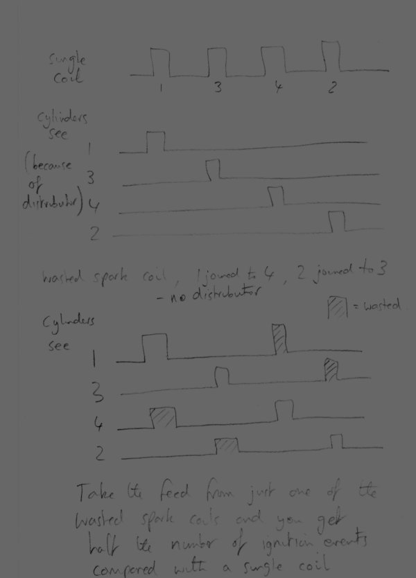
A standard tacho designed for a 4-pot, 4-stroke motor will show one revolution for every two igntion events, and thus two revs per four ignition events. A 1-3-4-2 cycle on a single-plane crank takes two full revolutions.
A wasted spark system has twice the number of igntion events per rev, so the same tach would show twice the revs at any given engine speed than on the engine above, if it was sensing pulses along the +ve feed to the coil pack.
Subsequently, if one -ve side of the coil was routed through the smiths pick-up, it would onlyt be sampling half of these events - two per rev - the same as with the stock coil.
I think we are missing something with this:
You're right in that there are four spark events per engine rev with the EDIS, however it is only four because two spark plugs
are connected to each coil.
The coil only has to discharge once to give two spark events. So as far it's concerned there are just two per rev, one from each coil.
So, I think that both coil trigger leads would need to be used to give the tacho enough pulses per rev.
**********
HOWEVER, I'm afraid that I seem to have proved that only one lead is needed, as my Smiths Tacho is working perfectly with just
the one lead through it's pickup loop. I just don't understand why it works.
**********
The tacho knows nothing about revolutions of the engine - it just measures how many sparks/ignition events there are per unit time, which is, from my diagrams, only the same between the conventional and wasted spark systems if you "join together" the outputs from both wasted spark coils.
...and Jonno has a tacho that he must have got from under the Magic Tree
Enough of this amateur-speak, where's the expert we need!
Jonno - are you definitely running the EDIS pin 10 or pin 12 to the coil through your tacho and not the main +12v feed that goes to the centre connection on the coilpack?
i have connected my Smith tacho today, is the factory grey 200km/h one that comes with Minis in the 80s, normally triggered by points, worked nice in my factory EFI setup (ECU grounds negative side of coil). i only had a 12Volt Zener at hand so i used this with the diode circuit. the tacho works untill it hits 3000RPM, than drops to 0, if the revs goes below 3000 the tacho is back to work.
i think the problem here is the Zener. tomorow i will remove it and see what happens.
my idea is that Smith needs 12V and at higer revs there is just not enough voltage to overcome the Zener so it drops out. but i don't have Zener with different voltages to test it
i think the problem here is the Zener. tomorow i will remove it and see what happens.
my idea is that Smith needs 12V and at higer revs there is just not enough voltage to overcome the Zener so it drops out. but i don't have Zener with different voltages to test it
Just been down to the garage and checked the wiring.
I have Pin 8 on the EDIS connected directly to the centre pin on the coil pack (+12V), I have Pin 10 on the EDIS connected directly to Coil A's pin, and Pin 12 on the EDIS runs through the loop on the back of the Smiths Tacho, and on to Coil B's pin on the coil pack.
The MJLJ is configured for a 4 cylinder engine. The Tacho is meant for a 4 cylinder engine. There is DEFINATELY just the one coil trigger cable running through it.
When I run the engine with the laptop attached, running the configurator software, the tacho agrees with the RPM meter on the software.
I fully accept that this is very, very odd, but it happens before my very eyes. I'm worried I'm going mad.
I have to say that I haven't revved beyond about 3,500 rpm, as the motor is newly put together, and the neighbours complain of 'thunderous' noises, but it certainly works correctly up to this point.
As it seems so unlikely that this should work OK, I'm going to go and examine everything yet again, and think it all through again before reporting back.
Well, it's long established how wasted spark works- the two coil packs share the sparking duty that one distributor based coil would handle, and specifically why the diode circuit is needed: to recombine the signal from the multiple coil packs.
If I was able to get my hands on Jon's car I would perform a number of direct measurements:
- Take some direct measurements of the signal the tach is receiving under it's current condition.
- Wire up the diode circuit as suggested and see if the RPM is the same.
- Measure the output from the original distributor coil, if possible.
I'm going with the assumption that Jon has done a thorough job of double/triple checking his wiring, so I would predict some sort of aberration is causing the observed effect. It would be weird but explainable!
That sound exaclty like the problem that martinm has mulled over in another thread.KLAS wrote:i have connected my Smith tacho today, is the factory grey 200km/h one that comes with Minis in the 80s, normally triggered by points, worked nice in my factory EFI setup (ECU grounds negative side of coil). i only had a 12Volt Zener at hand so i used this with the diode circuit. the tacho works untill it hits 3000RPM, than drops to 0, if the revs goes below 3000 the tacho is back to work.
As for my theory, it's purely based on the fact that the two combined coils of a pack a'la th ford one we use, fires twice as often as a coil in a standard system, thus sampling only half of these events would show that same number of events per period.
Last edited by Gilesy998 on Wed May 16, 2007 9:57 am, edited 1 time in total.
KLAS
Another theory floating around (see http://www.autosportlabs.org/viewtopic.php?t=1231 ...and yes it's my theory!) is that it's worth trying to connect your rev counter to the PIP line from EDIS to MJLJ
Can you have a go at that and report back?
Martin
Another theory floating around (see http://www.autosportlabs.org/viewtopic.php?t=1231 ...and yes it's my theory!) is that it's worth trying to connect your rev counter to the PIP line from EDIS to MJLJ
Can you have a go at that and report back?
Martin
KLAS
Yes, that's correct - if you're tacho really is "triggered by the points" i.e the 0-12v transitions and not the flyback voltage, the you might have better luck with using PIP.
But it's only a theory, so temporary wiring will be fine to start with.
I'm keen to know what happens, so report back!
Martin
maybe a stupid question and allready answered before: what is the difference between PIP and the tacho output? i use the tacho out to drive my Megasquirt and know that my tacho will not work using it as that was my first idea to get the tacho running.
and will it of any help to open a Smith and make pics? maybe someone can see something worth to know?
and will it of any help to open a Smith and make pics? maybe someone can see something worth to know?
Hi KLAS
Have a look at the (my) first post in the thread referenced above (http://www.autosportlabs.org/viewtopic.php?t=1231) which explains the difference between PIP and TACH OUT.
In simple terms, PIP is always a square wave and TACH OUT follows SAW so is a variable mark:space pulse train. The theory is that the mark:space ratio of TACH OUT gets too high at large advances, which are associated with higher rpms, and the tacho can't resolves the spaces (which are very narrow) and just reads zero.
I'd draw a picture if I was at home and scan it in, but I'm away for a few days. Maybe I'll try something tonight....
It could be interesting to look inside a tacho and see if there are any commercially-identifiable components so we can look up what they do and perhaps derive how the tacho works
Martin
Martin,
So earlier in this thread Svein posted a link to a site where they apparently dissected and analyzed these tachometers- they even offer 'repair' kits for them!
It looks like an interesting source of information, and also might explain why we're seeing varying behaviour here getting the tach signal to work if they indeed have marginal or unreliable circuits within.
Cheers,Svein wrote:Looks like a good source for Smiths rev counters
http://members.shaw.ca/tsmit/tachmod/tachmod0.html