
Hi,
I have a problem getting my Smiths rev counter to work. It needs the high volt kick back to work. I can read half revs when i connect to one coil - as expected. I have tried the wiring diagram with the two diodes and a zener, something strange happens - The rev counter reads 850rpm as normal on tick over but as soon as i push down on the accelerator the needle rises very slightly but then drops to zero and only when the revs have dropped to tick over will it read somthing. I have tried quick recovery diodes, placing a 2.2k resistor after the zener. If i try without the zener or the reisistor i get nothing. Can someone help please.
Thanks.
Triumph Spitfire 1500 Rev Counter
Moderators: JeffC, rdoherty, stieg, brentp
Hmm- the last time this was discussed the trick was to remove the zener. You'll probably find that discussion by searching. However, in your case it doesn't seem to be working?
I'll have to defer to the other experts here for the Smiths tachometer. Is there an adjustment pot on the back of the unit?
(You had a duplicate post, so I deleted it.. Fyi)
Regards,
I'll have to defer to the other experts here for the Smiths tachometer. Is there an adjustment pot on the back of the unit?
(You had a duplicate post, so I deleted it.. Fyi)
Regards,
Hi,
I have the rev counter out of the dash, there are four screws in a 'Y' formation on the back but nothing to suggest any are to make adjustments.
I've had a search for previous posts, could anyone suggest any other rated diodes that could work, as i said i have tried a couple of different types but there are so many to try it would take ages to guess the right one from pot luck. I'm definately new to electronics so am learning as i go along, Why is the suggested voltage rating for diode's on the diagram 400v, why wouldn't a lower rate be better?
Anyway, any suggestions greatly appreciated. . . . .
400v is definitely the right value for the diodes - it is the maximum voltage that the diodes can withstand in the reverse polarity direction before failure ie a high +ve voltage on the cathode - the bar end of the diode symbol
Each diode is subject to reverse polarity when the "other coil" is kicking back. As the high voltage kickback is in the low hundreds of volts, a 400v diode is fine and I wouldn't reduce it.
As to why you're seeing what you see, I'm not sure
What we really need is some reference information of how this (and other) rev counters work, and then I'm sure that something can be worked out. I've googled a bit for it but can't find anything of substance - maybe others will have better luck...
Perhaps another option would be to get one of the rev counters in question and perform more direct measurements and analysis?
The odd thing with the Smiths Rev Counter is that some people get them working with little effort, yet others continue to have problems.
Are there different variants of the Smiths Rev Counter where some of them work better for us? Are there any adjustments pots on the unit (inside or outside) that could help?
Is it the luck of the draw with different units out there factory calibrated in such a way that the marginal ones do not like the diode circuit?
I don't know if this helps, but I am using a Smiths Tacho which looks very similar to the one in the article,
however I am running it without fault in a very simple way.
The plastic insulated loop on the rear is usually for the wire from the distributor-to-coil wire to pass through.
I think the Tacho must pick up the signal via induction (?).
Anyway, I have routed one of the two EDIS coil cables through my bulkhead, and have passed it through
the loop. It has to pass through the correct direction, otherwise the Tacho appears dead.
Applying power to the tacho in the normal way gives a perfect reading - I've checked it against the configurator
display.
I agree it is weird.
I thought about it before I connected it at all, and decided that if it was going to work, both coil trigger
cables between the EDIS and coil pack would have to go through, to catch all triggers, just like the old
distributor cable did.
I thought I had put both through and it worked perfectly, so I started to neaten up the cabling. That's
when I found I had actually fed through one coil trigger cable and the earth!
So, I made up the loom so just the one coil trigger goes through the tacho pickup loop, and it works perfectly.
The MJLJ is working on 4 cylinder setup.
Been thinking, though: The old distributor shaft runs at half engine speed and gives four triggers to the coil per rev.,
which is therefore 2 triggers per engine rev. The EDIS gives twice as many triggers than needed (half wasted), so
if only one trigger cable is used for the tacho, it's the same as the distributor shaft running at half speed, isn't it?
I think I could have made that clearer...
I see what your saying about the wasted spark, but it is only per coil otherwise all 4 would be sparking with 3 wasted.
Very strange whats happening your end.
This thing about high voltage kick back - when i put a volt meter on the coil signal (-ve) i read about 13v and when i put the diode in it reads about 6-8v depending on the diode, i still don't get why i need diodes to cope with 400v kick back. Also what is the zener supposed to do when it can be used?
Just to clarify i am doing this right, i have taken two wires from two of the three wires that go into the "motorcraft" coil pack, ie not the 12v feed. These are the right wires I am supposed to be taking the reading from and isolating from each other to make the rev counter work?
You don't need diodes to cope with the flyback - you need diodes, as you say, to connect the coils together so that the rev counter see both sets of pulses but isolate them from each other.
You need 400v diodes because of the size of the flyback - use say 100v diodes and they'll fail internally, either going open or short circuit, neither of which will be much help to you.
http://www.picotech.com/auto/waveforms/ ... ition.html (plus the other waveforms at that site) is a useful thing to have a look at - it's not specifically wasted spark, but the principle is exactly the same
Surely in a standard distributor system there are only two pulses per rev generated by the coil, not four? For each cylinder to fire once, on a four-stroke otto cycle, it takes two complete revolutions of the crankshaft. In that case, using the -ve side of one primary of the coil pack in a wasted spark system gives the same two pulses as before.
I might be wrong, but it makes sense in my mind.
I might be wrong, but it makes sense in my mind.
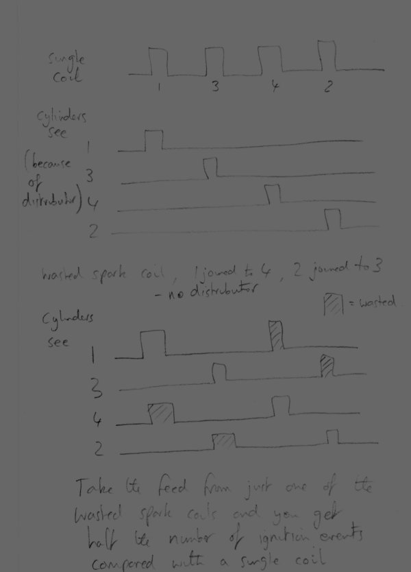
You made me draw it out to convince myself - so I might as well share it...
EDIT...where the 4 sparks in the dizzy take, as you say, 2 revolutions of the engine. But we're just looking at number of ignition events (however measured) per unit time, and from one of the wasted spark coils it is half as many as from the normal coil
EDIT...where the 4 sparks in the dizzy take, as you say, 2 revolutions of the engine. But we're just looking at number of ignition events (however measured) per unit time, and from one of the wasted spark coils it is half as many as from the normal coil
Last edited by MartinM on Tue May 15, 2007 7:54 am, edited 1 time in total.