
hi all,
i am just trying to get an installation up an running, so i would just like to get a couple of things straight first.
re load scale on ignition map.
*i take it the numbers are read as actual kPa readings, right?
*so for a n.a. setup, the highest number logically should be 100 kpa = 1 bar, which would be occur at WOT ie when there is no vacuum.
*conversely, the lowest number should be the lowest MAP/highest vacuum my motor makes, which will (in theory) occur at fully closed throttle at high rpm.
does that all sound correct?
and just fyi...
assuming it works, i have attached a photo of the trigger setup i am using. at this point i think i am having some trouble getting a clean signal from the vr sensor on account of the sensor and teeth being so tiny ie teeth are <1mm wide and gap between sensor and teeth is also <1mm. i dont have a laptop to plug in yet, which isnt assisting the process. i do, however, have an oscilloscope, but as i have only just bought it, i am not yet sure what it is telling me!
regards
alexander
sydney australia.
MAP sensor advance issues
Moderators: JeffC, rdoherty, stieg, brentp
MAP sensor advance issues
- Attachments
-
- reworked distributor (renault 807 motor in a lotus europa) using 72 tooth 30mm gearstock as a trigger wheel, and mazda rx7 CAS as the vr sensor.
- with clear cover.jpg (227.71 KiB) Viewed 14327 times
*i take it the numbers are read as actual kPa readings, right?
Correct
*so for a n.a. setup, the highest number logically should be 100 kpa = 1 bar, which would be occur at WOT ie when there is no vacuum.
Correct
*conversely, the lowest number should be the lowest MAP/highest vacuum my motor makes, which will (in theory) occur at fully closed throttle at high rpm.
Correct
*i am having some trouble getting a clean signal from the vr sensor on account of the sensor and teeth being so tiny...*
Wow - that's very impressive! Putting a 72-2 wheel in a distributor has often been talked about but I've never seen it, or heard of it being done.
However...
- what's it made of? Looks like brass - it needs to be ferrous. If it really is brass, I'd be surprised if it works at all
- they really are small teeth.
I think you're going to have to put an oscilloscope on the VR sensor output and see what signal you're getting - it should be sinusoidal with an obvious discontinuity when the missing tooth goes past (see http://www.bgsoflex.com/mjl/mjl_edis_summary.html). IIRC, the magnitude needs to be a minimum of about 1 volt peak to peak. With a 5.75" 5mm thick steel 36-1 wheel the signal increases amplitude with increased rpm going up to, IIRC, something in the region 10-20 volts.
You may need a signal conditioning circuit post sensor, pre-EDIS if your amplitude is too low.
Alternatively, I've often pondered using a slotted disc and an optical sensor inside a distributor - the VR sensor signal doesn't have to be sinusoidal due to the way it is processed, so a square wave will do (as long as it swings +ve to -ve and not just +ve to 0v). An optical setup would be relatively trivial to construct - a disc with 70 radial slots, two "non-slots" plus a IR LED and IR detector on opposite sides of the disc via in a U-shaped housing "on its side"
I'm exceedingly interested in this - I have someone with a Europa wanting to install a MJLJ but doesn't want to/can't use a standard 36-1 wheel
Correct
*so for a n.a. setup, the highest number logically should be 100 kpa = 1 bar, which would be occur at WOT ie when there is no vacuum.
Correct
*conversely, the lowest number should be the lowest MAP/highest vacuum my motor makes, which will (in theory) occur at fully closed throttle at high rpm.
Correct
*i am having some trouble getting a clean signal from the vr sensor on account of the sensor and teeth being so tiny...*
Wow - that's very impressive! Putting a 72-2 wheel in a distributor has often been talked about but I've never seen it, or heard of it being done.
However...
- what's it made of? Looks like brass - it needs to be ferrous. If it really is brass, I'd be surprised if it works at all
- they really are small teeth.
I think you're going to have to put an oscilloscope on the VR sensor output and see what signal you're getting - it should be sinusoidal with an obvious discontinuity when the missing tooth goes past (see http://www.bgsoflex.com/mjl/mjl_edis_summary.html). IIRC, the magnitude needs to be a minimum of about 1 volt peak to peak. With a 5.75" 5mm thick steel 36-1 wheel the signal increases amplitude with increased rpm going up to, IIRC, something in the region 10-20 volts.
You may need a signal conditioning circuit post sensor, pre-EDIS if your amplitude is too low.
Alternatively, I've often pondered using a slotted disc and an optical sensor inside a distributor - the VR sensor signal doesn't have to be sinusoidal due to the way it is processed, so a square wave will do (as long as it swings +ve to -ve and not just +ve to 0v). An optical setup would be relatively trivial to construct - a disc with 70 radial slots, two "non-slots" plus a IR LED and IR detector on opposite sides of the disc via in a U-shaped housing "on its side"
I'm exceedingly interested in this - I have someone with a Europa wanting to install a MJLJ but doesn't want to/can't use a standard 36-1 wheel
That trigger wheel is seriously TINY 
I would doubt you will get a good enough signal wave from that at all.
________
How to roll blunts
I would doubt you will get a good enough signal wave from that at all.
________
How to roll blunts
Last edited by -Ad- on Mon Feb 14, 2011 1:45 am, edited 1 time in total.
ok continuing on from comments i made in a different thread (doh)...
the wheel is a slice of carbon steel gearstock, which i purchased from an utterly incredible US on-line supplier of these things. man, the range of gears and gear stock they carry is unbelievable! i looks a bit like brass in the photo, but that is just the light. and, after all, if it wasnt ferrous, it wouldnt work with the vr sensor.
the sensor came out of a crank angle sensor from a mazda rx7 from the early 90s.
i have had a look at the waveform on an oscilloscope today, and it was quite well defined, save only that the amplitude varies a little over each rotation. i think that is a result of the tiny teeth, sensor and tiny amount of runout as the wheel rotates.
so far, the car starts, revs right out (but.... no tach working), has some issues with misfiring under acceleration, which disappears on full throttle.
watch this space!
alexander.
i took the gearstock to a motor reconditioning shop to cut it, and drill it. i asked them to drill it for an interference fit on the shaft, and left it to their discretion. then the goose tried to hammer it on to the stripped down distributor shaft, which he broke! luckily i had a spare, so i pressed it on to the shaft myself.MartinM wrote:(...to keep to the same thread!)
Did you use a dividing head and a mill to make that, or did you jump through hoops to make it on a lathe? I've only got the latter (and no dividing head).
How is it registered on the spindle?
Got any pictures of the car?
Excellent work though so far!
added in: i had waited for a month while another engine shop failed to do this simple job. the machinist there was an octogenarian italian who could barely be understood, and away either holidaying, or ill. so i took the untouched parts to another place nearby. to my dismay, the machinist there turned out to be another octogenarian italian, who was (of course) away on holidays. well he did come back, but he and the presumed son were like the italian steptoe and son. steptoe the elder was mumbling about how the gear should be fitted the shaft, and sort of objecting to it being hammered on, while steptoe the junior told him to nick off, and tried to belt it on with a hammer. then he broke the shaft. told me, with great surprise, that he thought the distributor shaft was mild steel!!! needless to say, i wont be going there for any head reconditioning work.
i will note this about the distributor i used: it is an australian bosch unit, fitted to australian renaults (local content rules at the time), and it is larger in diameter than the ducellier distributors which were used elsewhere in the world. there would not be room for these components in a ducellier distributor.
that said, someone on the europa yahoo group i read has installed a megajolt/edis by attaching a larger 72-2 wheel to the camshaft pulley on the renault motor. for the benefit of those who dont know, the renault motor in question - from an R16 - dont have a crank pulley at all. an alternative would be to have lugs welded to/screwed into, the periphery of the flywheel and sense them with a vr sensor mounted on the bellhousing. i think later renaults with electronic ignition did this.
alexander.
Last edited by alexander on Mon Jan 21, 2008 4:53 am, edited 2 times in total.
advance issues.... now talking about 72-2 wheels...
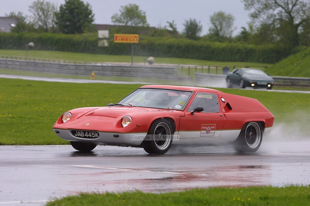
the car...
- Attachments
-
- Pa160115.jpg (122.17 KiB) Viewed 14282 times
Fantastic adaptation of EDIS- thank you for sharing!
I too would like to see the waveform from the sensor. A couple of things come to mind:
* Squareness of the teeth: I would expect the shape of the teeth would dictate the shape of the signal to a certain degree. We'll wait for the waveform plot, but I would imagine seeing fatter peaks of the teeth combined with fatter void (more square) would provide a crisper signal.
* Size of the sensor: I've always wondered how small the timing wheel could be for these standard VR sensors. At some point I'd expect multiple teeth simultaneously affecting the signal. The fact your engine runs with a stock crank sensor is noteworthy!
On the topic of optical sensors- I'm convinced this would work with a slotted disk. The EDIS module certainly works well with a digital simulator, so I would expect an optical arrangement would be no different.
Very cool stuff! Thanks again.
here is a photo of the trigger wheel and sensor close up.
notably, the teeth are already fairly square, certainly considering their size.
they are, to be precise, 1mm thick at the top of the tooth, and the valley is
about 1mm deep.
the sensor is also 1mm thick. in its original application, it was sensing teeth which were about 1.5mm thick, had a ratio of space to tooth of about 3:1, and valleys around 5mm.
i will try to capture the waveform with the digital camera, but it is certainly quite sinusoidal but with some variation in amplitude during each cycle, as noted above.
regards
alexander.
- Attachments
-
- sensor&trigger wheel close up.jpg (63.07 KiB) Viewed 14238 times
hi brent, for posterity, these are the parts i used:
first, the gearstock:
Thanks for shopping with http://www.sdp-si.com. We'd like to
confirm your order and provide you with some useful information.
On 12/20/2006, you ordered:
Part Number Quantity Unit Price Extension
------------------------------------------------------------------------
A 1C29MY05072 1 $46.36/Each $46.36
------------------------------------------------------------------------
Subtotal: $46.36
Shipping: *
Handling: $3.95
Sales Tax ( NY State Only ): $0.00
.. the part is about 250mm long; i had a 25mm piece cut from it, and drilled to suit.
if only for interest, have a look at the website for the amazing range of gears and gearstock!!!
secondly, the sensor is from a Mazda FC series RX7, crank angle sensor.
the thing looks like a distributor, with a flat metal plate instead of the cap.
bonus! there are two identical sensors in side. one for you, one for a friend...
caution! i am having problems with sporadic missing under acceleration, AND the dreaded USB/serial converter freezing the programming software. as noted above, however, these exact parts were used in a successful EDIS/ megasquirt installation by someone whose word i trust.
regards
alexander.
Thank you for the part numbers.
Noting the measurement of the gear above- Some time back I milled up a small gear from scratch from a piece of plate steel, for purposes of constructing a 'mini' test bench, fitting to a small electric motor. It's about the same size as the gear you pictured. I'll dig it up and snap a picture.
Noting the measurement of the gear above- Some time back I milled up a small gear from scratch from a piece of plate steel, for purposes of constructing a 'mini' test bench, fitting to a small electric motor. It's about the same size as the gear you pictured. I'll dig it up and snap a picture.
Hi Alexander
I'd pop over and give you a hand - but I'm about 10,600 miles away at the moment.
But I will be in Sydney in November* - will that do?
Martin
* - me and the current Mrs MartinM are doing a big trip mid-Oct to mid-Dec (London-Beijing-HK-Sydney-Cairns-Auckland-Fiji-London). To be honest, I might not get away with a MJLJ-diversion in Aus, but on the other hand, we might have had enough of each other by then that it might be a Good Thing! Will post a pic of my mate's Europa in a mo.....
..for lots of other stuff about my mate and his Lotuses, type "beadsmoore lotus" into Google....
...and for his latest car (arriving in the UK this week...and not a Lotus)
http://www.gt40s.com/forum/rcr-forum-rc ... rcr70.html
...and for his latest car (arriving in the UK this week...and not a Lotus)
http://www.gt40s.com/forum/rcr-forum-rc ... rcr70.html