One Ignition 12v supplying edis/coilpack/mjlj

EDIS and Megajolt installation related topics. Be sure to review the <a href="http://www.autosportlabs.net/MJLJ_V4_vehicle_installation_guide">Vehicle installation guide</a>

Moderators: JeffC, rdoherty, stieg, brentp

-Ad-
Posts: 33
Joined: Tue Nov 27, 2007 4:07 pm
Location: UK

One Ignition 12v supplying edis/coilpack/mjlj

Post by -Ad- »

Is this ok to do?

I assume so, as long as the single ignition live 12v is thick enough to handle the current pull of the edis/coilpack and mjlj ecu?

Or could i use a Permanent Battery live to the above components/\ Through a relay that i could switch with my original ignition 12v?
Like so:

Image
What size fuse would i need, mj has 15a, edis has 15a, coil has 5a i think?
________
400gt
Last edited by -Ad- on Mon Feb 14, 2011 1:44 am, edited 1 time in total.

MartinM
Posts: 433
Joined: Sat Aug 27, 2005 12:08 pm

Post by MartinM »

Not really recommended.

Single fuse to EDIS and coilpack - 15A for a 4-cylinder

Single fuse to MJLJ - 5A (or even 3A if you can get one)

All running from a switched positive (live when in "ignition" and "cranking" positions)

-Ad-
Posts: 33
Joined: Tue Nov 27, 2007 4:07 pm
Location: UK

Post by -Ad- »

So can the Ign 12v of the EDIS and coilpack be wired to one point.
And then the MJ ecu to another ignition live?

Its just a case of finding another suitable ignition live 12v then
________
Honda Capa Specifications
Last edited by -Ad- on Mon Feb 14, 2011 1:44 am, edited 1 time in total.

MartinM
Posts: 433
Joined: Sat Aug 27, 2005 12:08 pm

Post by MartinM »

You can use the same ignition live point - just use two fuses.

One side of each fuse to the live point.
The other side of the 15A fuse to EDIS and coilpack
The other side of the 5A fuse to MJLJ

-Ad-
Posts: 33
Joined: Tue Nov 27, 2007 4:07 pm
Location: UK

Post by -Ad- »

Ok mate, cheers.

Thats one less thing to sort then, cheers :)
________
DIGITAL VAPORIZER
Last edited by -Ad- on Mon Feb 14, 2011 1:44 am, edited 1 time in total.

steve100
Posts: 26
Joined: Mon Jan 09, 2006 9:52 pm

Post by steve100 »

That's a big fuse rating.
My bench test showed a current draw of 1.05 Amps at 3000rpm (EDIS4) - this was MJ, EDIS & coil pak combined.

david jenkins
Posts: 204
Joined: Tue Feb 14, 2006 2:14 pm
Contact:

Post by david jenkins »

I use one 12v supply with a 5A fuse for the lot - hasn't blown yet, and works OK.

...but, you watch, now that I've said that... :(

brentp
Site Admin
Posts: 6277
Joined: Wed Jan 24, 2007 6:36 am

Post by brentp »

You are probably slowly stressing that 5A fuse. For bench work I've had to use a >8A switching power supply to keep up with the demand- these power supplies are extremely eager to shut down in overcurrent situations, unlike simple linear power supplies which just exhibits voltage sag when over-driven.

MartinM
Posts: 433
Joined: Sat Aug 27, 2005 12:08 pm

Post by MartinM »

Simple Ohms Law with a 0.5R primary coil resistance gives a nominal current of 12v/0.5R = 24 Amps

- if the coil is switched on permanently (not a standard mode of operation with EDIS admittedly) then this is the current that will flow. So that is why most traditional ignition systems (dizzy/points/coil) are protected with a circa 30A fuse - so that the ignition can be turned on with the engine off and the points closed

- the peak currents in the coil in normal low rpm (EDIS/MJLJ) conditions is circa 11 Amps (see http://www.bgsoflex.com/igncoil.html)

Hence 15A seems a reasonable compromise - above normal operating values but not too far above.

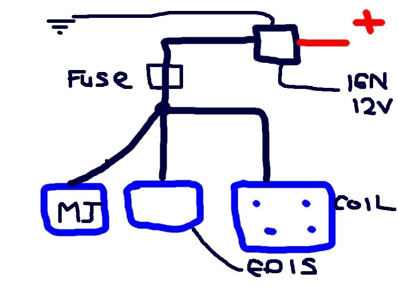
Personal experience with the MJLJ is that if you have some sort of short inside the unit, the first thing to blow is the PCB tracks which is tricky to repair. MJLJ draws virtually no current (30-40mA) normally so you should use a very low fuse - hence my suggestion for a fuse in the region of 3A to 5A. Protect MJLJ with a 15A fuse (original suggestion) would be fine - but the MJLJ is likely to decompose pretty badly before the fuse blows in some failure modes :eek:

So I'd still advocate that the 'proper' solution is two fuses - 15A for EDIS/coil and 5A for MJLJ.

YMMV, $0.02 etc etc

steve100
Posts: 26
Joined: Mon Jan 09, 2006 9:52 pm

Post by steve100 »

seems to me the EDIS /coil sys / trigger is a lot different to the std kettering coil / points setup. On EDIS, if you slowly rotate the engine insuffiently fast to cause a spark there is no point at which the coil resistance is connected to the power supply ie O amps - unlike, as you say, with a conventional ign system on an engine is stationary with the points closed you see 20 + amps. On kettering the higher the revs the lower the amps isnt it?


All I'd say is that I never saw the amps quoted even when very slowly turning the engine just sufficient to get the coil to fire. (I monitored the battery supply voltage too and that hardly moved more than a few .1 volts)

I'm only going on what I saw on my meters. I was envisioning using a 10A circuit breaker or fuse for the whole system. with a 3-5A fuse tee'd off down stream of the main fuse just to the MJ unit for the reasons given. That way you use less cable & , if the MJ fails & fuses, the rest of the coil /edis system will stay live for the limp home mode.
:)

david jenkins
Posts: 204
Joined: Tue Feb 14, 2006 2:14 pm
Contact:

Post by david jenkins »

Brent,

Maybe this information would be very useful in the installation guide?

Fortunately it would be quite easy to modify my supply wiring, but I'm sure that many others wouldn't be so lucky.

cheers,
David

brentp
Site Admin
Posts: 6277
Joined: Wed Jan 24, 2007 6:36 am

Post by brentp »

Agree it would be a good update to the wiring diagram, so it's on the to-do list.

I will list 15-20A for powering the coil + EDIS. 1-5A for the MJLJ.

In principal, the EDIS+MJLJ could be powered from the same 5A fuse since the EDIS module's current consumption is likely close to what the MJLJ consumes (haven't measured it). It is the coil pack which actually has the higher current draw. However, in some installations the packaging, wiring and component placement considerations may make it easier to hang the EDIS module off of the same circuit as the coil pack, e.g. if the EDIS module is mounted close to the coil pack.

Martin, what shorted out internally that blew a trace? Was it a 5V or 12V section of the board?

Thanks,
Last edited by brentp on Thu Jan 17, 2008 5:42 pm, edited 1 time in total.
Brent Picasso
CEO and Founder, Autosport Labs
Facebook | Twitter

Ken555
Posts: 92
Joined: Fri Sep 07, 2007 8:24 pm
Location: Aberdeenshire
Contact:

Post by Ken555 »

Been thinking about this, in the context of the way I have the Rev Limiter module fitted.

my coil pack is now powered Via the megajolt unit connector.
i.e the supply comes in via Pins 7 & 6 feeds both the megajolt and rev limiter Internally.

Because of this I fitted a 15 amp fuse on the feed instead of the 3amp I had ( see
http://www.autosportlabs.org/viewtopic.php?t=1479 )

Might it be better/safer to isolate the pins and use, say, pin 6 for the megajolt fused at 3A and pin 7 for the limiter fused at 15A ?

Will need to look at the limiters schematics and see where the coil power comes from.

brentp
Site Admin
Posts: 6277
Joined: Wed Jan 24, 2007 6:36 am

Post by brentp »

The +12V Input for the rev limiter connects to the same circuit the coil pack would normally be driven from- i.e. it's connected 'in-line' so it can drop the coil's current consumption when activated.

If installed internally to the case (which is not required, of course), then yes- the MJLJ is fed from the 15A supply. Alternatively, the rev limiter could be installed in close proximity to the coil pack and wired in-line.
Brent Picasso
CEO and Founder, Autosport Labs
Facebook | Twitter

Ken555
Posts: 92
Joined: Fri Sep 07, 2007 8:24 pm
Location: Aberdeenshire
Contact:

Post by Ken555 »

In which case I would be better off splitting pins 6 & 7, and independently fusing each one.

Post Reply